AX3500 Motor Controller User’s Manual 125
Data Logging in R/C Mode
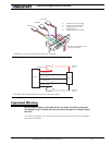
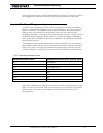
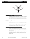
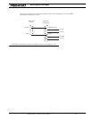
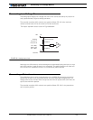
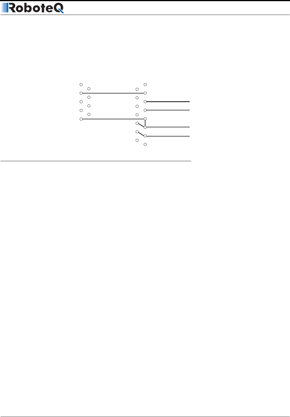
PC’s communication port. Figure 84 and below shows the wiring diagram of the modified
R/C cable for connection to a PC.
1
2
3
4
7
8
9
5
1
2
3
4
5
6
7
8
9
10
11
12
13
14
15
6
RX Data
RS232 Data Out
GND
R/C Ch 1
R/C Ch 2
R/C GND
R/C +5V
GND
DB9 Female
To PC
DB15 Male
To Controller
FIGURE 84. Modified R/C cable with RS232 output for data logging to a PC


