Using the Roborun Configuration Utility
184 AX3500 Motor Controller User’s Manual Version 1.9b. June 1, 2007
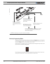
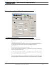
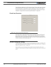
featuring the additional Analog Inputs 3 and 4 are automatically identified as Rev. B in this
area of the screen.
3- Parameter Selection and Setting and Special Functions
This is the program’s main frame and includes several types of tabs, each of which has sev-
eral buttons, menus and other User Interface objects. These tabs and the functions they
contain are described in detail in the following sections.
Navigate from one set of commands to another by clicking on the desired tab.
4- File and Program Management Commands
This frame contains a variety of buttons needed to load and save the parameters from and
to the controller or disk. This frame also contains the button needed to initiate a software
update to the controller.
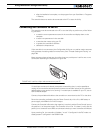
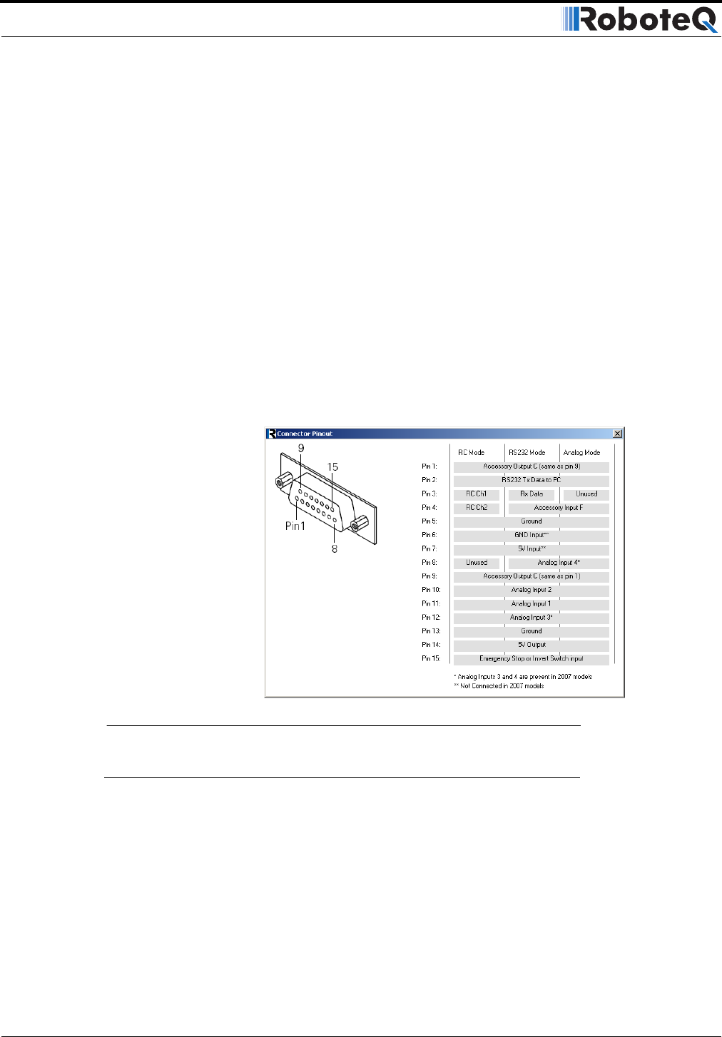
5- View Controller Connector Pinout
Clicking on this link will conveniently pop a window containing the Controller’s connector
pinout.
Getting On-Screen Help
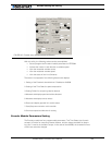
The Roborun buttons and fields are very intuitive and self-explanatory. Additional explana-
tions and help is provided by means of ToolTips for several of command. Simply move the
cursor to a button, tab or other gadget on the screen and a message box will appear after a
few seconds.
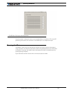
FIGURE 102. Roborun screen layout


