Chapter 4 Maintaining the Sun Fire V40z Server 4-27
4. If you are installing the CPU card as a new option, skip to Step 8.
If you are replacing an existing card, continue with the next step.
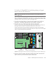
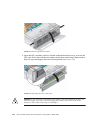
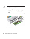
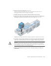
5. Open the two plastic levers on the CPU card corners simultaneously to release it
from its backplane, then carefully pull it out of the server (see
FIGURE 4-17).
FIGURE 4-17 Removing the CPU Card From the Chassis
6. Set the CPU card on an ESD-resistant surface.
7. Remove any replaceable components (CPUs, memory modules, VRMs) from the
old CPU card and set them aside on an ESD-resistant surface.
Refer to the following procedures:
■ “Replacing a Memory VRM on the CPU Card” on page 4-42
■ “Replacing a CPU VRM on the CPU Card” on page 4-47
■ “Replacing a Memory Module on the CPU Card” on page 4-52
■ “Replacing a CPU on the Optional CPU Card” on page 4-58
8. Install components to the new CPU card (either as new components or as
components you are transferring from an old CPU card).
Refer to the following procedures:
■ “Replacing a Memory VRM on the CPU Card” on page 4-42
■ “Replacing a CPU VRM on the CPU Card” on page 4-47
■ “Replacing a Memory Module on the CPU Card” on page 4-52
■ “Replacing a CPU on the Optional CPU Card” on page 4-58


