Chapter 4 Maintaining the Sun Fire V40z Server 4-79
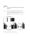
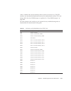
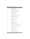
TABLE 4-3 defines the activity indicators that are shown in FIGURE 4-41. The LED
numbers are intentionally duplicated between the motherboard and the CPU card.
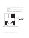
Jumper J125, the clear-CMOS jumper, is explained in “Clear-CMOS Jumper” on
page 4-80.
All other jumpers and switches are for internal factory troubleshooting and are
intentionally not documented in this guide.
TABLE 4-3 Indicators on the Motherboard and CPU Card
Indicator Number Component Activity Indicated
LD8 CPU1 or CPU3
LD9 CPU1 or CPU3 CPU VRM
LD10 CPU1 or CPU3 memory VRM
LD11 DVD drive
LD12 CPU 1 or CPU3 memory slot 0
LD13 CPU 1 or CPU3 memory slot 1
LD14 CPU 1 or CPU3 memory slot 2
LD15 CPU 1 or CPU3 memory slot 3
LD16 CPU0 or CPU2
LD17 CPU0 or CPU2 CPU VRM
LD18 CPU0 or CPU2 memory VRM
LD20 CPU0 or CPU2 memory slot 0
LD21 CPU0 or CPU2 memory slot 1
LD22 CPU0 or CPU2 memory slot 2
LD23 CPU0 or CPU2 memory slot 3
LD25 PCI slot 1
LD26 PCI slot 2
LD27 PCI slot 3
LD28 PCI slot 4
LD29 PCI slot 5
LD30 PCI slot 6
LD31 PCI slot 7


