


Chapter 4 Maintaining the Sun Fire V40z Server 4-43
Caution – The electronic components and solder joints on the bottom of the CPU
card are fragile. Use care to avoid scraping the bottom of the CPU card on the
chassis or door when removing or installing it.
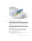
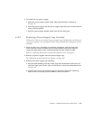
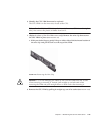
4. Open the two plastic levers on the CPU card corners simultaneously to release it
from its backplane, then carefully pull it out of the server (see FIGURE 4-17).
5. Set the CPU card on an ESD-resistant surface.
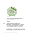
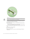
6. Identify the memory VRM that must be replaced.
The memory VRM is in the outer slot, furthest from the CPU.
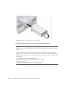
7. Remove a memory VRM by pressing down on the ejector bars at both ends of the
socket (see
FIGURE 4-28).
8. Install the new VRM to the socket by pressing down firmly and evenly on both
top corners, until the ejector levers close over the notches on the VRM.
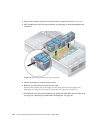
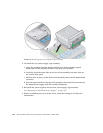
9. Replace the CPU card into the server (see
FIGURE 4-18):
a. Carefully align the rear corners of the CPU card with the plastic alignment
tracks inside the server chassis, then slide the CPU card into the tracks.
b. Press in firmly and evenly on both corners of the CPU card until it engages the
backplane.
c. Lock down the two plastic latches on the corners of the CPU card to secure it in
place.
10. Close the CPU card door.
11. Replace the front bezel onto the server.