


Chapter 4 Maintaining the Sun Fire V40z Server 4-59
Caution – The electronic components and solder joints on the bottom of the CPU
card are fragile. Use care to avoid scraping the bottom of the CPU card on the
chassis or door when removing or installing it.
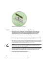
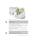
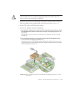
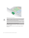
4. Open the two plastic levers on the CPU card corners simultaneously to release it
from its backplane, then carefully pull it out of the server (see FIGURE 4-17).
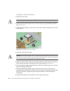
5. Set the CPU card on an ESD-resistant surface.
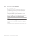
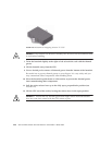
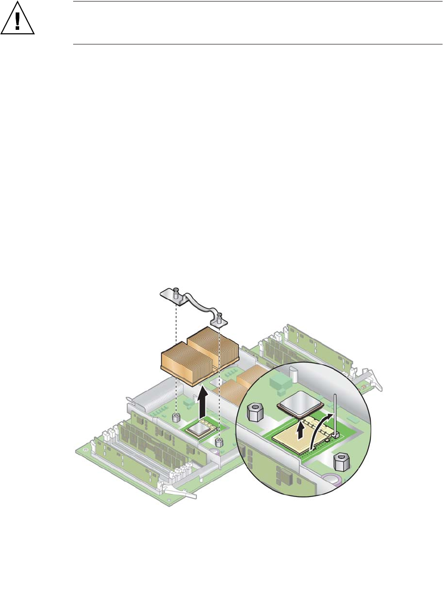
6. Unscrew the heatsink from the motherboard.
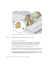
a. For a heatsink installed on an auxiliary CPU card in the original release (chassis
PN 380-1010) of the Sun Fire V40z server (for CPUs of stepping versions “C0”
and “CG”):
Unfasten the two securing screws and remove the heatsink securing clip. See
FIGURE 4-35.
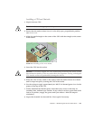
b. For a heatsink installed in the updated release (chassis PN 380-1206) of the
server (for CPUs of stepping versions “E”):
Loosen the screws evenly on each side of the heatsink. Remove the screws and
captive springs that secure the heatsink (the washers remain fixed to the surface
of the heatsink). See
FIGURE 4-36.
FIGURE 4-35 Removing the Securing Clip and Heatsink for Stepping Versions “C0” and
“CG” CPUs