


6-36
EM18-33010A
6. DIAG. TEST OPERATION
(Revision Date: Jan. 14 ‘99)
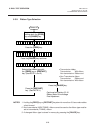
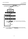
6.3 PARAMETER SETTING MODE
NOTE: The following operation cannot be performed unless the sensor type is changed by the issue
command or feed command.
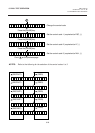
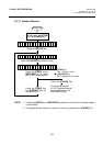
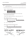
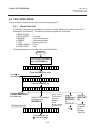
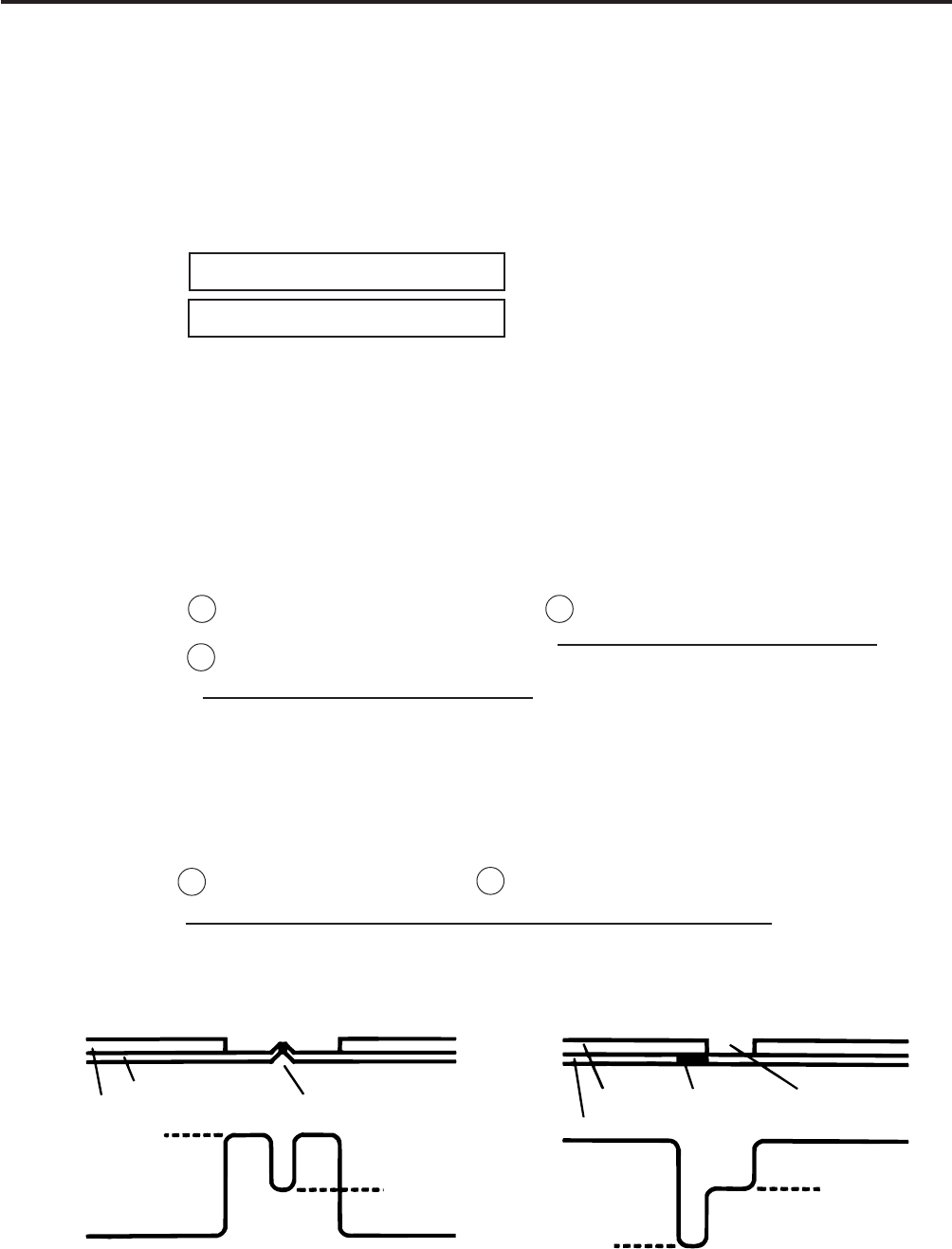
(1) Using the sensor adjustment in Diag. mode, measure the sensor voltage at the following four points.
Label: Print area Backing paper
Tag paper: Print area Black mark
Example:
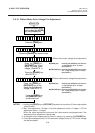
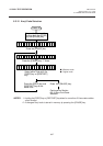
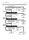
(2) Using the following formula, calculate the threshold from the measured voltage:
When using labels (transmissive sensor):
Threshold = (Max. voltage at the backing paper) - (Voltage at the print area) - 0.7V
e.g.) 2.0V = 4.2V - 1.5V - 0.7V
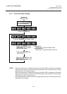
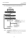
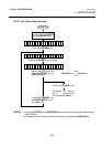
When using perforated labels (transmissive sensor):
Threshold = (Max. voltage at the backing paper) Min. voltage at the backing paper
Max. voltage at the backing paper
e.g.) 2.2V = 4.4V - (2.8V/2) - (1.6V/2)
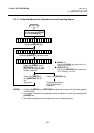
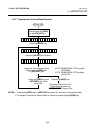
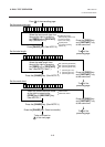
When using labels with black marks (reflective sensor):
Threshold = (Min. voltage at the print area) - (Min. voltage at the black mark)
e.g.) 0.4V = (1.5V - 0.7V)/2
[ R E F L E C T I V E ] 2 . 8 V
[ T R A N S M I S S I V E ] 4 . 1 V
2
2
2
-
-
A
A
B
C
D
Backing Parper
Label
Perforation
B
(2.8 V)
A
(4.4 V)
D
(0.7 V)
C
(1.5 V)
Backing Paper
Label
Black Mark Label gap