


4-1
4. DIP SWITCH FUNCTIONS
EM1-33035
4. DIP SWITCH FUNCTIONS
WARNING:
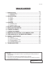
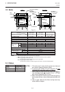
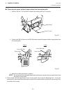
Turn the POWER OFF before switching the functions.
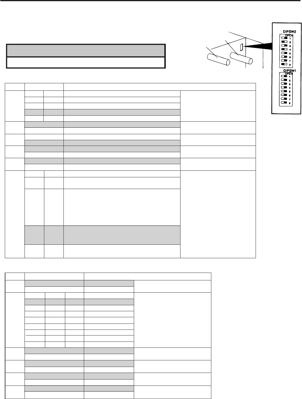
Fig. 4-1
4. DIP SWITCH FUNCTIONS
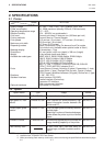
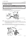
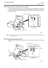
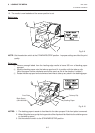
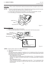
The DIP switches are located to the right of the supply shaft.
(1) DIP SW 2
(2) DIP SW 1
NOTES: 1. The shaded settings are the factory default settings. "OFF" means "OPEN".
2. The DIP switch #1-6 functions in accordance with equipment to be used.
3. If you would like to switch to READY/BUSY (DTR) or to READY/BUSY (RTS) of data protocol,
please contact your authorized TOSHIBA TEC representative.
Supply Shaft
Ribbon Shaft
No.
1
2
3
4
5
6
7
8
2400 BPS
4800 BPS
9600 BPS
19200 BPS
1 bit
2 bit
7 bit
8 bit
without
with
EVEN
ODD
XON/XOFF(No XON is output at the power on time.)
(XOFF is output at the power off time.)
READY/BUSY (DTR)
(No XON is output at the power on time.)
(No XOFF is output at the power off time.)
READY/BUSY (RTS)
(No XON is output at the power on time)
(No XOFF is output at the power off time.)
XON/XOFF + READY/BUSY
(XON is output at the power on time.)
(XOFF is output at the power off time.)
XON/XOFF(XON is output at the power on time.)
(XOFF is output at the power off time.)
Transmission speed
Stop bit length
Data length
Parity check
Parity check (effective when DIP
SW #5 is set to ON.)
Data protocol
ON/OFF
OFF
ON
OFF
ON
OFF
ON
OFF
ON
1
OFF
ON
OFF
ON
2
OFF
ON
ON
ON
Function
7
OFF
ON
OFF
ON
8
OFF
OFF
ON
ON
No.
1
2
3
4
5
6
7
8
Without
With
English
German
French
Dutch
Spanish
Japanese
Italian
Not used
Without
With
Without
With
Must be set to OFF.
Must be set to OFF.
Auto ribbon save function
Language to display LCD error
message
Auto media feed after a cut issue
(See page 6-5)
Use of the built-in rewinder/Head up
function in cut mode Refer to Note 2.
ON/OFF
OFF
ON
OFF
ON
OFF
ON
OFF
ON
OFF
ON
2
OFF
ON
OFF
ON
OFF
ON
OFF
ON
Function
3
OFF
OFF
ON
ON
OFF
OFF
ON
ON
4
OFF
OFF
OFF
OFF
ON
ON
ON
ON