


3-1
EM18-33010A
3. INSTALLATION PROCEDURE FOR THE OPTIONAL EQUIPMENT
3. INSTALLATION PROCEDURE FOR THE OPTIONAL
EQUIPMENT
(Revision Date: Feb. 10, 2000)
3.1 HIGH SPEED PC INTERFACE BOARD (B-4800-PC-QM)
WARNING!
Make sure to unplug the power cord before installing the optional equipment.
3.1 HIGH SPEED PC INTERFACE BOARD (B-4800-PC-QM)
The high speed PC interface board can be used together with the IBM PC-AT or its compatible machine
only.
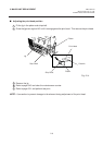
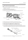
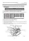
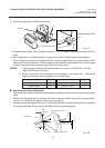
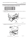
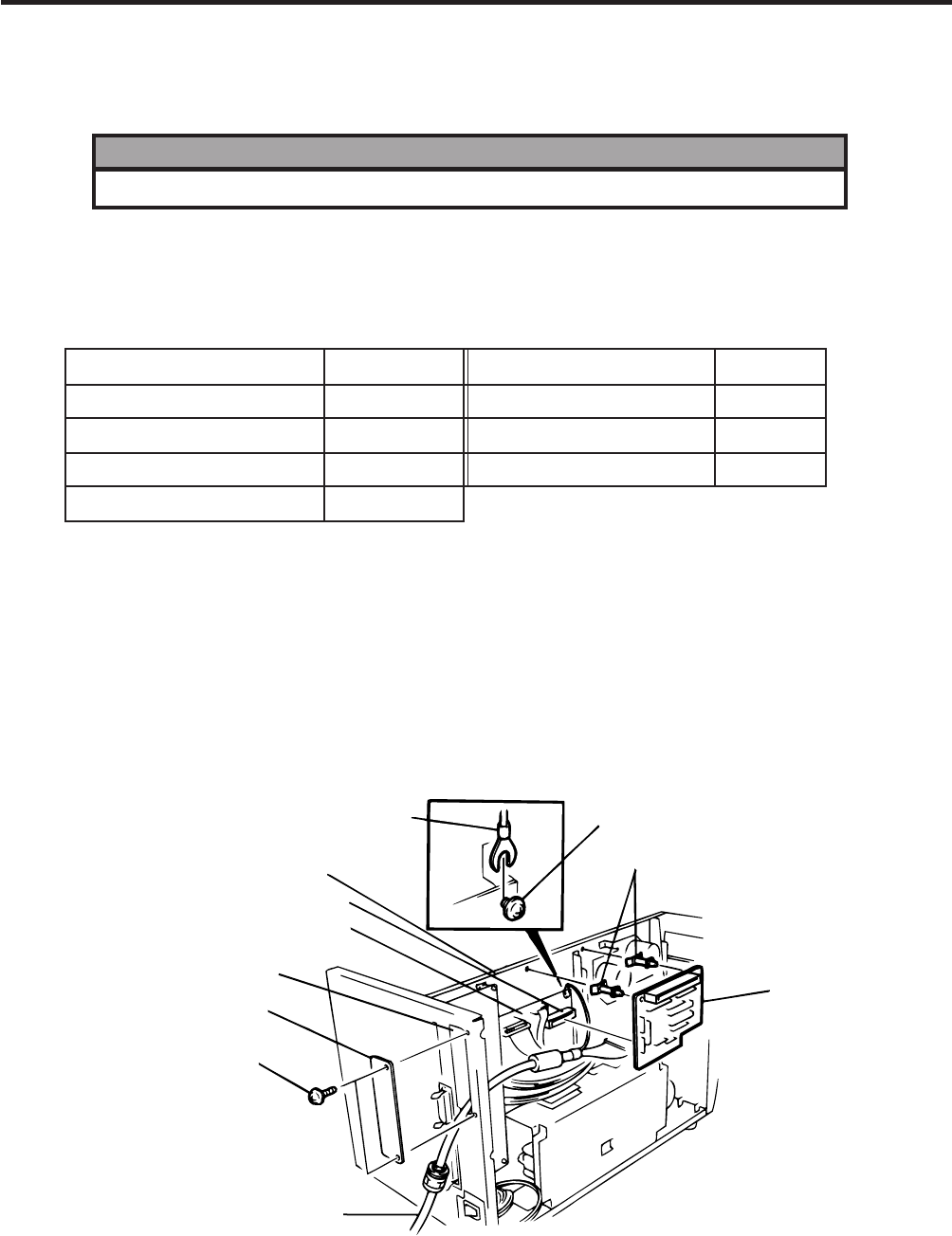
1. Remove the top cover and left side cover. (See Fig. 2-1.)
2. Remove the two FL-3x5 screws to detach the blind plate.
3. Pass the printer cable through the opening.
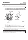
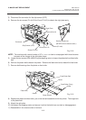
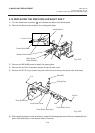
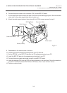
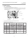
4. Fasten the ground wire of the printer cable to the CPU PC board at the upper right with the SM-3x6B
screw securing the CPU PC board.
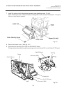
5. Attach the two locking supports to the main frame plate. Install the BPE PC board aligning with the
connector (CN10) and locking supports.
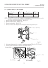
Fig. 3-1
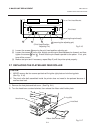
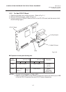
Description
BPE PC board
BPC PC board
Printer cable
Cable support
Q’ty/Unit
1
1
1
1
Q’ty/Unit
2
1
1
Description
Locking support
Program diskette
Owner’s Manual
Ground Wire
Main Frame Plate
Screw (SM-3x6B)
Locking Supports
Connector (CN10)
Opening
Blind Plate
Screw (FL-3x5)
Printer Cabel
CPU PC Board
BPE PC Board