


2-10
EM18-33010A
2. MAJOR UNIT REPLACEMENT
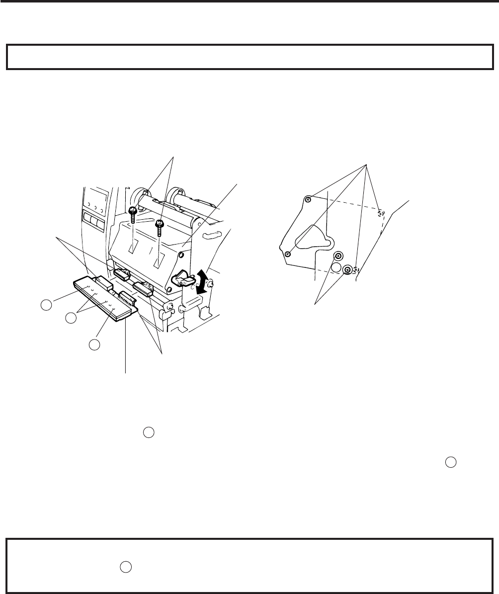
Fig. 2-15
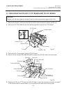
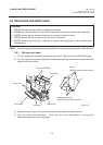
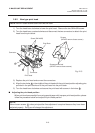
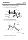
2.6.2 New type print head
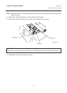
1) Turn the head lever clockwise to lower the print head. Remove the two SM-4x8B screws.
2) Turn the head lever counterclockwise and disconnect the two connectors to detach the print
head from the print block.
(Revision Date Feb. 01, ’96)
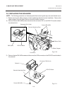
2.6 REPLACING THE PRINT HEAD
NOTE: NEVER loosen screws other than two SM-4x8B.
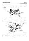
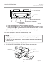
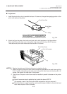
3) Replace the print head and connect the connectors.
4) Align the two holes A in the middle of the print head with the print head position adjusting pins
provided in the print block and fit the print head into the print block.
5) Turn the head lever clockwise and secure the print head with screws in the holes B .
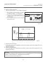
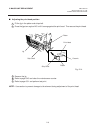
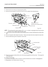
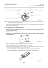
■ Adjusting the print head position
When print tone becomes light from using special paper with improper print head position, please
follow the procedure below and adjust the print head position.
NOTE:
Never loosen screws C unless print position fine adjustment is required because they have been
adjusted properly. Doing so will change the adjustment.
Screw (SM-4x8B)
Screws
(NEVER remove these screws.)
Screws painted red
(NEVER remove these screws.)
Connector
Print Block
A
Connector
B
B
Print Head