


Page
EM18-33010A
(Revision Date: Dec. 10 '99)
CAUTION:
1. This manual may not be copied in whole or in part without prior written permission of
TOSHIBA TEC.
2. The contents of this manual may be changed without notification.
3. Please refer to your local Authorized Service representative with regard to any queries
you may have in this manual.
TABLE OF CONTENTS
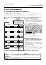
6. DIAG. TEST OPERATION.................................................................................. 6- 1
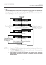
6.1 OUTLINE OF THE DIAG. TEST OPERATION ........................................... 6- 1
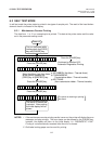
6.2 SELF TEST MODE ..................................................................................... 6- 3
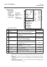
6.2.1 Maintenance Counter Printing.......................................................... 6- 3
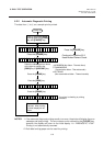
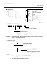
6.2.2 Automatic Diagnostic Printing .......................................................... 6- 6
6.2.3 Head Broken Element Check .......................................................... 6-12
6.3 PARAMETER SETTING MODE ................................................................ 6-13
6.3.1 Feed Length Fine Adjustment ......................................................... 6-15
6.3.2 Cut/Strip Postion Fine Adjustment .................................................. 6-16
6.3.3 Back Feed Length Fine Adujustment .............................................. 6-17
6.3.4 X Axis Fine Adjustment ................................................................... 6-22
6.3.5 Print Tone Fine Adjustment............................................................. 6-24
6.3.6 Character Code Selection ............................................................... 6-25
6.3.7 Font Zero Selection ......................................................................... 6-26
6.3.8 Control Code Selection ................................................................... 6-27
6.3.9 Ribbon Type Selection .................................................................... 6-29
6.3.10 Ribbon Motor Drive Voltage Fine Adjustment ................................. 6-30
6.3.11 Strip Wait Status Setting ................................................................. 6-31
6.3.12 Stacker Selection ............................................................................ 6-32
6.3.13 Threshold Manual Fine Adjustment for the Black Mark Sensor ...... 6-33
6.3.14 Threshold Manual Fine Adjustment for the Feed Gap Sensor ........ 6-34
6.3.15 Kanji Code Selection ....................................................................... 6-37
6.3.16 Euro Font Code Selection ............................................................... 6-38
6.3.17 Transmission Control Mode Selection ............................................ 6-39
6.3.18 Reset selection when the INPUT • PRIME Signal is ON ................ 6-40
6.4 TEST PRINT MODE .................................................................................. 6-41
6.4.1 Normal Test Print ............................................................................ 6-41
6.4.2 Process Test Print ........................................................................... 6-46
6.5 SENSOR SETTING MODE ........................................................................ 6-48
6.5.1 Thermistor Check ............................................................................ 6-48
6.5.2 Black Mark Sensor Adjustment ....................................................... 6-49
6.5.3 Feed Gap Sensor Adjustment ......................................................... 6-50
6.5.4 Paper End Setting for Black Mark Sensor....................................... 6-51
6.5.5 Paper End Setting for Feed Gap Sensor ........................................ 6-52
6.6 RAM CLEAR MODE .................................................................................. 6-53
6.6.1 Maintenance Counter Clear ............................................................ 6-55
6.6.2 Parameter Clear .............................................................................. 6-56