


2-12
EM18-33010A
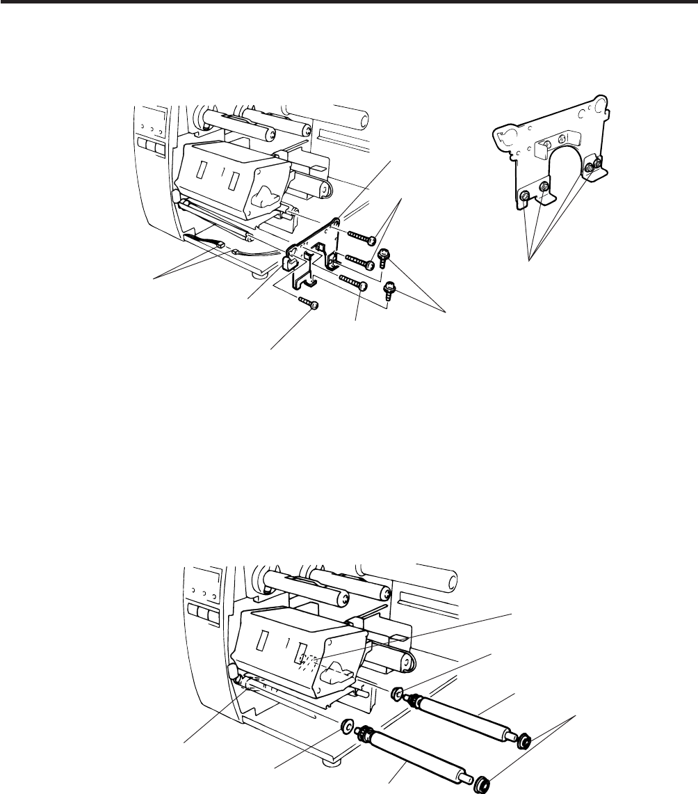
2. MAJOR UNIT REPLACEMENT
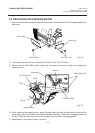
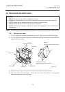
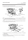
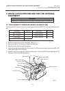
3) Disconnect the connector for the strip sensor (LED).
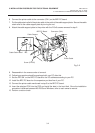
4) Remove the six screws (FL-4x6, B-4x12 and P-3x12) to detach the right plate ass’y.
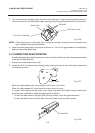
NOTE: The machine with a serial number of 4T x x x x x x or later is not equipped with the red screws
because of the change in the right plate shape.
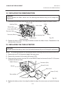
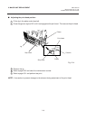
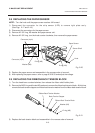
5) Loosen the two screws (SM-4x8B) fixing the stepping motor to loosen the platen belt and feed roller
belt.
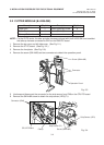
6) Remove the platen belt to detach the platen. Remove the feed roller belt to detach the feed roller.
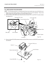
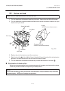
7) Remove both bearings from the platen or feed roller.
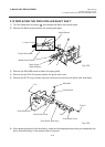
8) Replace the platen and feed roller, put on the belt and assemble it with the printer. The longer belt
is the platen belt.
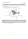
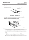
9) Attach the right plate.
10) Hold down the stepping motor and secure it so that the belts have no slack or disengagement.
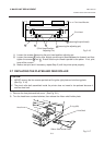
11) Reassemble in the reverse order of removal.
Fig. 2-18
Fig. 2-19
(Revision Date Sep. 29, ‘95)
2.7 REPLACING THE PLATEN AND FEED ROLLER
Connector
Strip Sensor (LED)
Screw (P-3x12)
Screw (B-4x12)
Right Plate
Screw (B-4x12)
Screw (FL-4x6)
Screws painted red
(NEVER remove these screws.)
Feed Roller Belt
Holder
Feed Roller (Gray)
Holder
Platen (Black)
Holder
Platen Belt