


1-10
1. OUTLINE OF THE SYSTEM
EM10-33006A
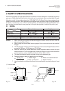
1.5 ELECTRONICS SPECIFICATIONS
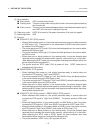
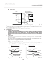
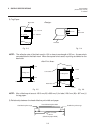
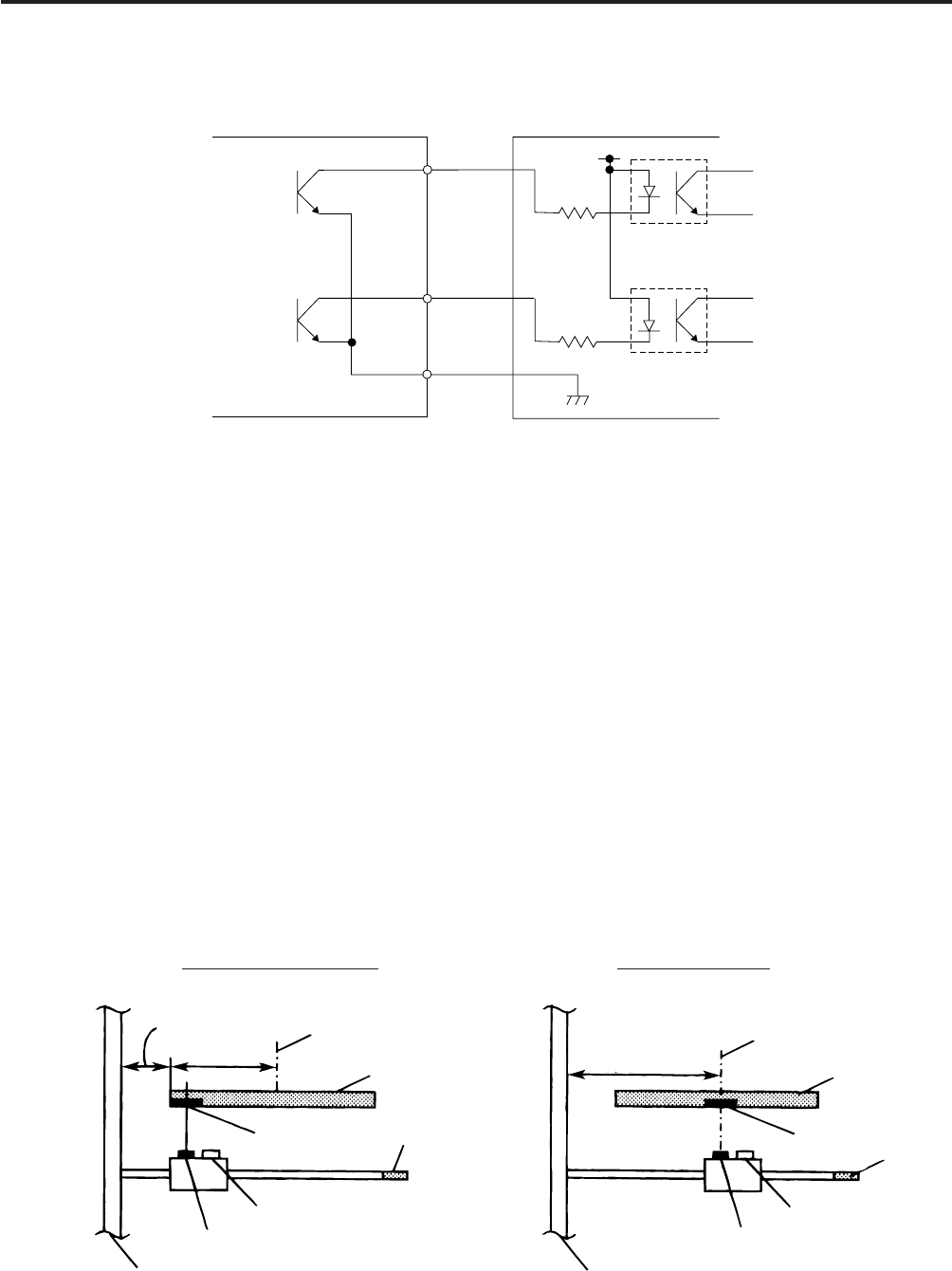
External controller, etc.
(In case of photo-coupler)
~
~
Printer
OUT0
OUT5
COM2
Vcc
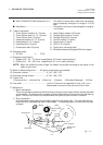
■ Output circuit
Fig. 1-9
There are six output circuits, and each output is an open collector. The voltage of Vcc is 24 V (max.)
while the operating current is 150 mA.
For other details, please refer to the Expansion I/O specification.
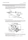
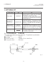
4) Sensor/switch
1 Head up switch (micro switch)
This switch, attached at the lower left of the print head as viewed from the media outlet, detects
that the print head is ready to print (head is down). When the head lever is lowered, the head
down cam pushes up the print head, the micro switch is turned on and the print head prepares
to print.
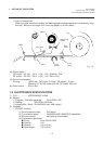
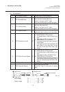
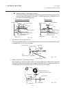
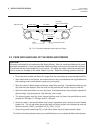
2 Paper sensor
This sensor is comprised of the black mark sensor and feed gap sensor. It is positioned 92.1
mm from the platen.
The sensor position is adjustable according to the media width. It moves toward the main
frame a max. of 70 mm by turning the knob counterclockwise.
■ Black mark sensor (Reflective sensor)
This sensor detects the difference of potential between the black mark and tag paper to
find the print position of the tag paper.
It is located at the home position with the tag paper or print head before shipment.
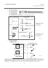
Side detection (max.) Center detection
Fig. 1-11
Fig. 1-10
20.5 mm
70 mm
Tag Paper
Center
Knob
Feed Gap Sensor
Black Mark Sensor
Main Frame
Black Mark
90.5 mm
Center
Tag Paper
Black Mark
Knob
Feed Gap Sensor
Black Mark Sensor
Main Frame