


2-14
EM18-33010A
2. MAJOR UNIT REPLACEMENT
(Revision Date Sep. 29, ’95)
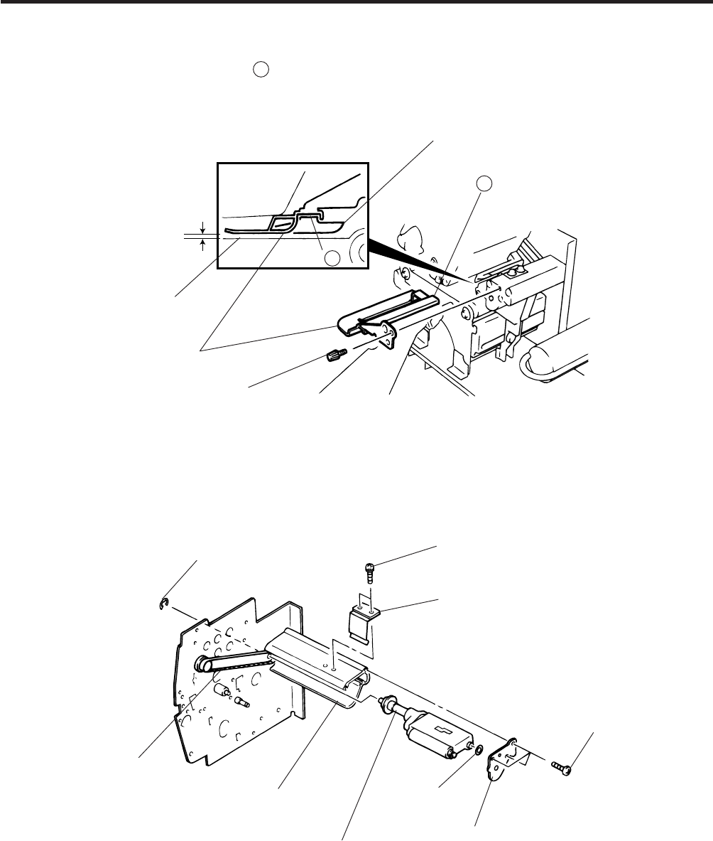
2.10 REPLACING THE PINCH ROLLER SHAFT ASS’Y
2.10 REPLACING THE PINCH ROLLER SHAFT ASS’Y
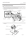
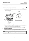
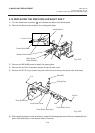
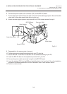
1) Turn the head lever to position 3 , and release the ribbon shaft holder plate.
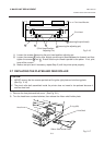
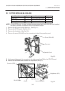
2) Remove the black screw to detach the media guide plate.
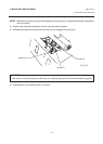
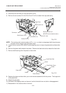
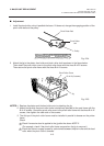
3) Remove the SM-4x8B screw to detach the spring plate.
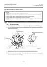
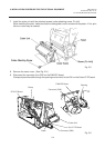
4) Remove the six B-4x12 screws to detach the pinch roller cover.
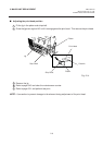
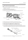
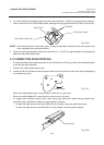
5) Remove the E-5 E-ring to loosen the pinch roller belt, and remove the pinch roller shaft ass’y.
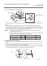
6) After replacing the pinch roller shaft ass’y, make the following adjustment while you reassemble the
pinch roller shaft ass’y in the reverse order of removal.
Fig. 2-22
Fig. 2-23
B
Media Sensor
Black Screw
(HAA-0004001)
B
Media Guide Plate
Printer Block Base
1.5 mm~2.5 mm
SM-4x8B
Spring Plate
B-4x12
E-5
Pinch Roller Belt
Pinch Roller Cover
Pinch Roller Shaft Ass’y
W-8
Pinch Roller Cover