


2-13
EM18-33010A
2. MAJOR UNIT REPLACEMENT
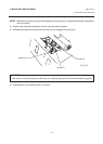
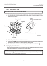
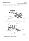
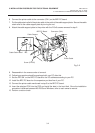
5) Replace the paper sensor and reassemble in the reverse order of removal.
6) After replacing the paper sensor, refer to page 6-32/6-33 and adjust the voltage.
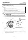
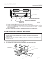
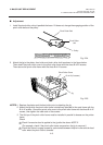
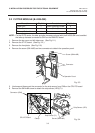
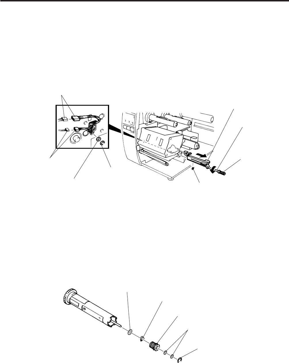
2.9 REPLACING THE RIBBON BACK TENSION BLOCK
1) Turn the head lever counterclockwise, then release the ribbon shaft holder plate.
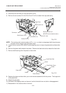
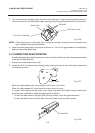
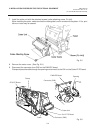
2) Remove the M3 E-ring and the two M3 washers to remove the ribbon back tension block. At this time,
remove the back tension stopper and ribbon back tension washer from the ribbon back tension block.
Fig. 2-20
Fig. 2-21
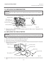
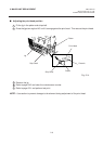
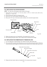
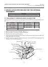
2.8 REPLACING THE PAPER SENSOR
2.8 REPLACING THE PAPER SENSOR
NOTE: Turn the knob until the paper sensor reaches full forward.
1) Disconnent the connector for the strip sensor (LED) to remove right plate ass’y.
(See Figs. 2-17 and 2-18.)
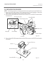
2) Disconnect the connectors for the paper sensor.
3) Remove M1.5 E-ring, M3 washer and paper sensor unit.
4) Remove M1.5 E-ring, turn the knob counter clockwise, then remove the paper sensor.
3) Replace the back tension block and reassemble in the reverse order of removal.
Paper Sensor
Sensor Shaft
Knob
E-ring (M3)
E-ring (M3)
Washer (M3)
Connector (2 pin)
Connector (4 pin)
Ribbon Back Tension Washer
Back Tension Stopper
Ribbon Back Tension Block
E-ring (M3)
Washer (M3)