


3-3
EM18-33010A
3. INSTALLATION PROCEDURE FOR THE OPTIONAL EQUIPMENT
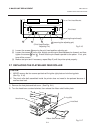
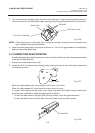
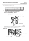
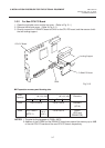
5. Unclamp and disconnect the connector for the strip sensor from CN6 on the CPU PC board.
6. Remove the SM-4x6B screw to detach the strip sensor (LED)/(Tr).
Fig. 3-3
Fig. 3-4
(Revision Date: Feb. 10, 2000)
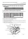
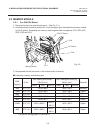
3.2 CUTTER MODULE (B-4205-QM)
3.2 CUTTER MODULE (B-4205-QM)
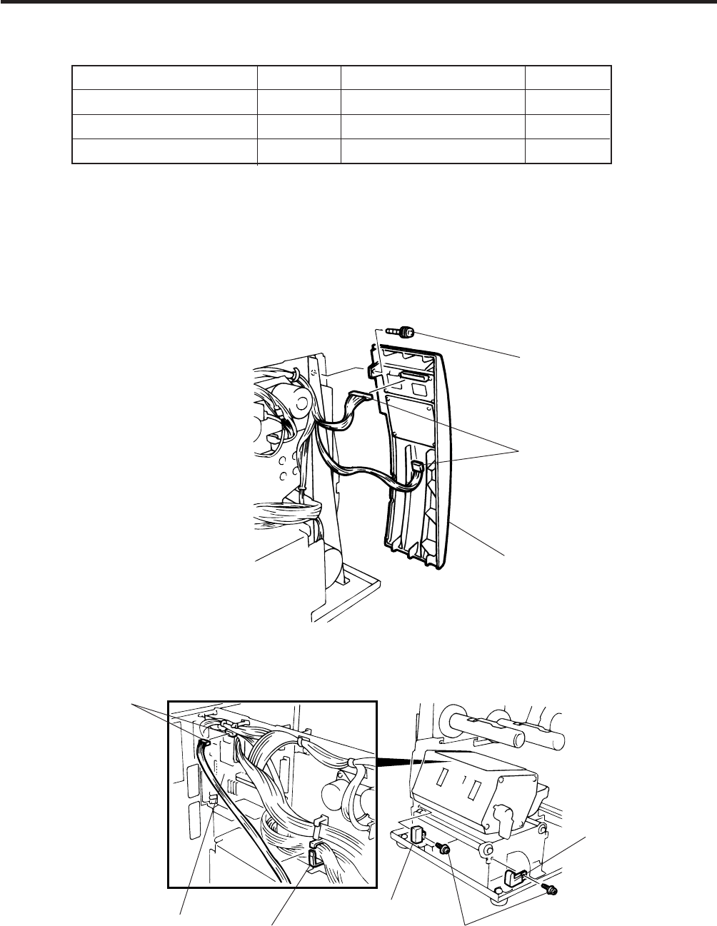
NOTE: For the B-570 series, the take-up/cutter harness enclosed with the B-4205-QM is not used but
the take-up harness connected to CN2 on the PWM PC board.
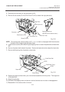
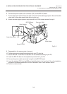
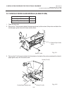
1. Remove the top cover and left side cover. (See Fig. 2-1.)
2. Remove the I/F PC board. (See Fig. 2-2.)
3. Remove the front plate. (See Fig. 2-6.)
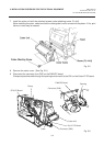
4. Remove the screw (SM-4x8B) and two connectors to detach the operation panel.
Description Q’ty/Unit Description Q’ty/Unit
Cutter Unit 1 Cutter Attaching Screw 2
Cutter Cover 1 Screw (FL-4x6) 1
Take-up/Cutter Harness 1 Cleaner 1
Screw (SM-4x8B)
Connector
Operation Panel
Connector (CN6)
CPU PC Board
Clamp
Strip Sensor (Tr)
Screw (SM-4x6B)
Strip Sensor (LED)