


1-8
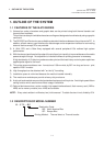
1. OUTLINE OF THE SYSTEM
EM10-33006A
(Revision Date: Aug. 5 '99)
1.5 ELECTRONICS SPECIFICATIONS
SN75189 or equivalent
RD
CTS
DSR
TD
RTS
DTR
SN75188 or equivalent
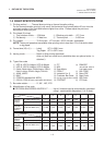
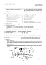
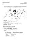
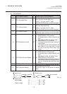
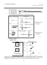
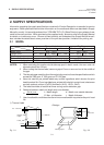
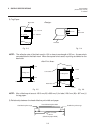
(10) Interface circuit
■ Input circuit ■ Output circuit
Fig. 1-6
■ Signal level
Input voltage "H" ..................... + 3V ~ + 15V
"L"...................... - 3V ~ -15V
Output voltage "H" ..................... + 6V ~ + 13V
"L"...................... - 6V ~ -13V
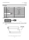
Pin No.
1
2
3
4
5
6
7
20
Signal
FG (Framed Ground)
RD (Received Data)
TD (Transmit Data)
CTS (Clear to Send
RTS (Request to Send)
DTR (Data Terminal Ready)
SG (Signal Ground)
DSR (Data Set Ready)
Description
Ground line for circuit protection.
Data line from which the priter receives data
from the host (receive data line).
Logic "1" is "Low", and "0" "High".
It is LOW (MARK) while no data is being sent.
Data line from which the printer sends data to
the host (send data line).
Logic "1" is "Low", and "0" "High".
It is LOW (MARK) while no data is being sent.
Input signal from the host.
It must be "High" for the printer to send data.
Output signal to the host.
(1) READY/BUSY (DTR) protocol
It indicates there is data to send to the
host.
After power is ON, it is always "High".
(2) READY/BUSY (RTS) protocol
Indicates whether the printer is ready to
receive data.
The signal is at the Low level when the
data amount in the data buffer is near
full, and at the high level when near
empty.
Output signal to the host.
(1) READY/BUSY (RTS) protocol
It indicates there is data to send to the
host.
After power is ON, it is always "High".
(2) READY/BUSY (DTR) protocol
Indicates whether the printer is ready to
receive data amount in the data buffer is
near full, and at the high level when near
empty.
Ground line for all data and control signals.
Input signal from the host.
It must be "High" for the printer to receive
data.
I/O
-
I
O
I
O
O
-
I
(9) Pin description