


2-15
EM18-33010A
2. MAJOR UNIT REPLACEMENT
(Revision Date Sep. 29, ’95)
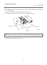
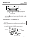
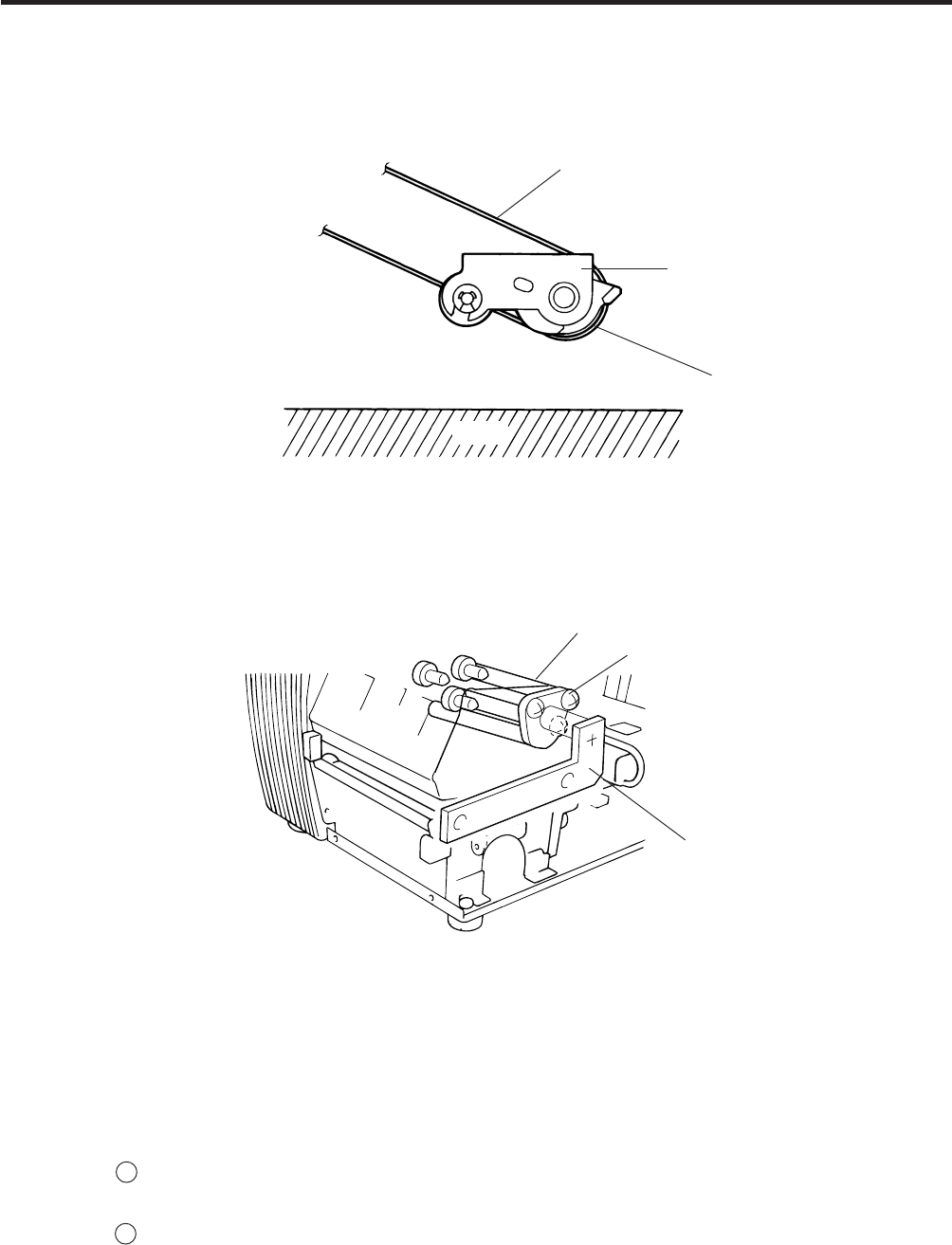
2.10 REPLACING THE PINCH ROLLER SHAFT ASS’Y
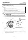
■ Adjustment
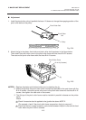
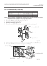
1. Install the pinch roller unit so it parallels the base. If it does not, change the engaging position of the
pinch roller belt and the pulley.
Fig. 2-24
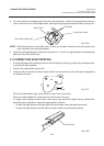
Fig. 2-25
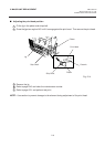
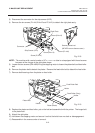
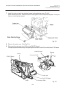
2. Attach the jig to the platen, feed roller and pinch roller shaft as shown in the figure below.
Then attach the pinch roller cover to the pinch roller frame with the three B-4x12 screws.
Then secure the pinch roller frame with the three B-4x12 screws.
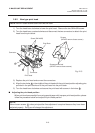
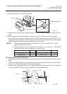
NOTES:1. Replace the platen and the feed roller prior to attaching the jig.
2. Attach the jig while the pinch roller frame is tentatively attached to the main frame with the
B-4x12 screws. Secure the pinch roller cover to the pinch roller frame with the three B-4x12
screws, then tighten the other side of the screws.
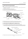
3. The flat top of the pinch roller frame must be installed in parallel to bosses on the printer
frame.
Check
1 Check if excessive load is applied to the jig after the above NOTE 2.
(For example, check if the pinch roller frame moves when the jig is removed.)
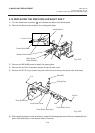
2 Check that there is no gap caused by a slant shaft between the pinch roller and the feed
roller when the pinch roller is lowered.
Pinch Roller Belt
Pinch Roller
Unit
Pulley
Pinch Roller Cover
B-4x12 (6 screws)
Jig
Base