


2-2
EM18-33010A
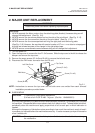
2. MAJOR UNIT REPLACEMENT
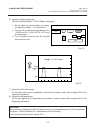
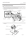
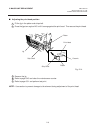
3) Disconnect the 13 connectors from the CPU PC board.
4) Remove the six screws (SM-3x6B, SM-3x6C) to detach the CPU PC board from the printer.
(Revision Date: Feb. 10, 2000)
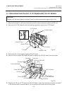
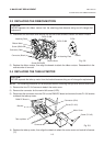
2.1 REPLACING THE PS UNIT, I/F PC BOARD AND CPU PC BOARD
2.1 REPLACING THE PS UNIT, I/F PC BOARD AND CPU PC BOARD
CAUTION:
Replace only with same type and ratings of fuse for continued protection against risk of fire.
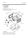
1) Remove the three FL-4x6 screws and disconnect the two connectors to detach the PS unit.
2) Remove the FL-3x5 screw and the four locking supports to remove the I/F PC board.
Fig. 2-2
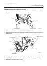
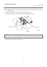
5) Replace the PS unit, I/F PC board and CPU PC board. Insert the connectors correctly and install
in the reverse order of removal above. Do not mount the left side cover and top cover.
Fig. 2-3
PS Unit
Screw (FL-4x6)
Screw (FL-3x5)
I/F PC Board
Screw (FL-4x6)
Connector
Locking Support
Screw (SM-3x6B)
Screw (SM-3x6B)
CPU PC Board
Connector
Connector
Connector
Screw (SM-3x6B)
Connector
Connector
Connector
Screw (SM-3x6C)
Screw (SM-3x6B)
Connector