


4.1 General 4 Replacement Procedures
TECRA M1 Maintenance Manual (960-436) 4-1
4 Replacement Procedures
4.1 General
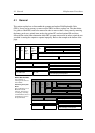
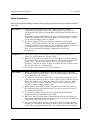
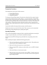
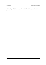
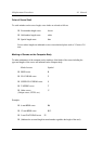
This section explains how to disassemble the computer and replace Field Replaceable Units
(FRUs). It may not be necessary to remove all the FRUs in order to replace one. The chart below
is a guide to which FRUs need to be removed in order to remove others. Always start by removing
the battery pack, next, optional items such as the optional PC card and optional SD card, then
follow the line on the chart to determine which FRU you must remove next in order to repair the one
you think is causing the computer to operate improperly. Refer to the example at the bottom of the
page.
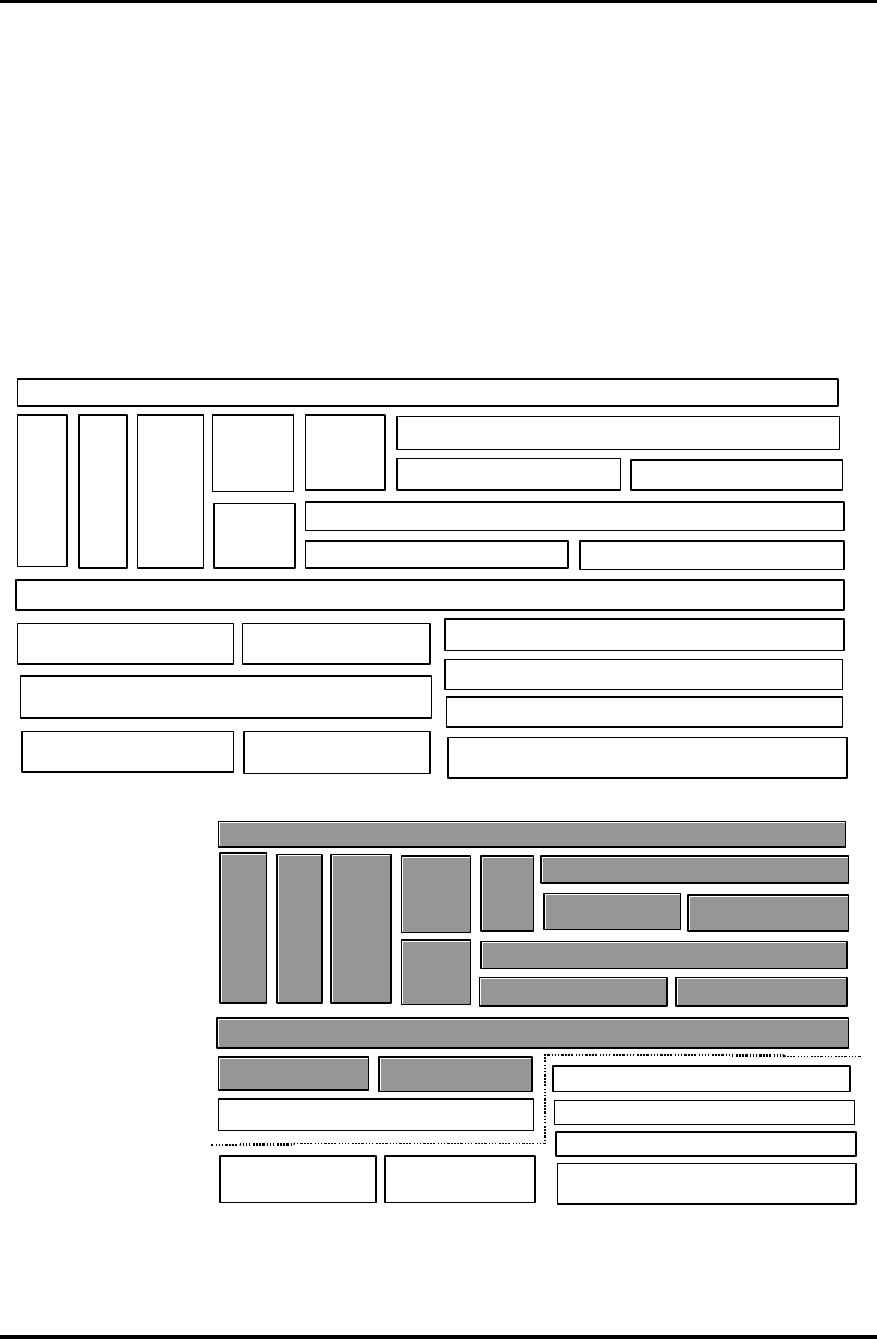
How to See the Chart
Two examples of
referring to the chart are
shown below.
•
Removing the System
Board
First, 4.2 Battery to 4.14
Bluetooth must be
removed. Then remove
4.15 Display Assembly,
4.16 LED Board and 4.17
Sound Board to remove
the System Board.
4.2 Battery
4.3
PC
Card
4.4
SD
Card
4.6
Slim
Select
Bay
module
4.5
HDD
4.7
Modem
Daughter
Card
4.20 Fan
4.8
CPU
4.9 Keyboard
4.10 Memory Module
4.13 Wireless LAN card 4.14 Bluetooth module
4.11 Sensor/Switch Board
4.15 Display Assembly
4.12 Touch Pad
4.16 LED Board
4.19 USB Board
4.17 Sound Board
4.21 Display Mask
4.22 FL Inverter
4.23 LCD Module
4.24 Wireless LAN Antenna/Bluetooth
Antenna/Display Cover/Speaker
4.18 System Board/RTC Battery/DC-IN Jack
4.2 Battery
4.3
PC
Card
4.4
SD
Card
4.6
Slim
Select
Bay
module
4.5
HDD
4.7
Modem
Daughter
Card
4.20 Fan
4.8
CPU
4.9 Keyboard
4.10 Memory
Module
4.13 Wireless LAN card 4.14 Bluetooth module
4.11 Sensor/Switch
Board
4.15 Display Assembly
4.12 Touch Pad
4.16 LED Board
4.19 USB Board
4.17 Sound Board
4.21 Display Mask
4.22 FL Inverter
4.23 LCD Module
4.24 Wireless LAN Antenna/Bluetooth
Antenna/Display Cover/Speaker
4.18 System Board/RTC Battery/DC-IN Jack