


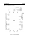
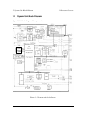


1 Hardware Overview 1.2 System Unit Block Diagram
1-12 TECRA M1 Maintenance Manual (960-436)
– Deeper Sleep (C4) Support
– Suspend/Resume Control
– AC'97 2.2 Interface
– Internal RTC
– Internal LAN Controller (WfM2.0)
– 421-ball 31×31mm BGA Package
q PC Card Controller Gate Array
• One YEBISU3S gate array is used.
• This gate array has the following functions and components.
– PCI interface (PCI Revision2.2)
– CardBus/PC Card controller (Yenta2 Version2.2)
– SD memory card controller (SDHC Ver.1.2)
– SD IO card controller (Ver.1.0)
– SmartMedia controller (SMHC Ver.01/SMIL1.0)
– SIO (UART) controller (MS Debug Port Specification Ver.1.0)
– Docking station interface
– Q switch control, reset control
– External device interface
q Firmware Hub (FWH)
• One Intel 82802AB8 is used.
• This gate array has the following features:
– Intel platform compatibility
– Firmware hub hardware interface mode
– Industry-standard packages
– Two configurable interfaces
– 4Mbits of flash memory for platform code/data nonvolatile storage
– Address/Address-Multiplexed (A/A Mux) interface/mode
– Case temperature operating range
– Vcc: 3.3V ± 0.3V
– Vpp: 3.3V and 12V for fast programming (80 hours maximum)
• 4Mbits of flash memory are used as shown below:
– 64KB are used for VGA-BIOS.
– 192KB are used for system BIOS.
– 8KB are used for plug and play data area.
– 8KB are used for password security.
– 16KB are used for boot strap.
– 64KB are used for ACPI P code.
– 64KB are used for LOGO.
– 64KB are reserved for LAN BIOS.