


42 P640i Card Printer User Guide 980541-001 Rev. A
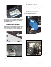
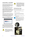
2. Using the manual card transport knob, drive a
card under the head and leave it there. With the
card under the head - make sure it’s there - turn
the adjustment screw to elevate the left end of the
head bracket to the point where your CR-80 feeler
gauge just slides under the bracket. Test the
mechanical setup by running the card back to the
hopper, then slowly out again. There should be a
barely perceptible upward movement of the
bracket as it rides up over the tapered pick edge of
the truck, see diagram on preceding page.
3. Load a few cards with magnetic stripe.
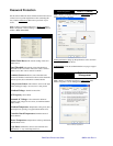
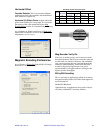
4. Click Mag Position Adjust
. The printer will then:
a. Pick a card from the hopper
b. Mag encode it
c. Back up, then run it under the read/write head
again to determine the position at which the
mag encoding begins
d. Eject the card through the laminator. The
starting position is stored in firmware and is
used for all subsequent mag operations
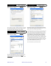
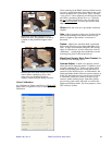
5. Click Mag Amplitude Adjust. The printer will
then:
e. Pick a card from the hopper
f. Mag encode it
g. Back up, then run it under the read/write head
again to measure average maximum
amplitudes of the recorded data displayed on
the Mag Data Monitor below
h. Pause for a few seconds to allow adjustment
i. Back up again, and repeat the read cycle
continuously until the PRINT button is
pressed, after which the card is ejected
through the laminator
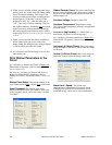
6. Turn the adjusting screw first clockwise then
counterclockwise in quarter-turn increments
while observing the data monitor. With the
bracket setup described in Step 2 above, it is pos-
sible that there will little change in amplitude
even with a full turn or two of the screw in either
direction.
• If there is no appreciable change, press the
PRINT button to end the test, then restore the
default setup of Step 2 using the CR-80 card
shim.
• •If the amplitude varies as you turn the screw,
tune for maximum values.
All three tracks should read at least 130. If there are
track-to-track differences greater than 10, the head
may be defective, or skewed in the bracket. If skewing
is the problem, loosen the lock nuts on the clamp
screws (diagram, preceding page), back out the screws
a turn or two, then carefully free the head (which may
have a light adhesive film on the surfaces mating with
the bracket). Position the head with its rim a hair
below the edges of the bracket, then retighten the
clamp screws and lock nuts.
7. Complete the procedure by re-running Mag Posi-
tion Adjust as in Step 4 above.
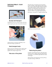
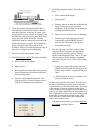
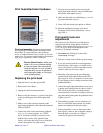
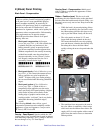
Adjustomg screw
(3/32" hex wrench)
Shim
The “shim” is a narrow strip of CR-80 card.
It must be removed before running the printer.