44 P640i Card Printer User Guide 980541-001 Rev. A
Techncial Note 4 - Print Station
The print head is a precisely machined slice of
ceramic, on the bottom edge of which is a row of tiny
heating elements (resistors), 300 to the inch. A thin
glaze coating protects the heating elements. Under
normal operating conditions the head is capable of
printing many thousands of images.
Damage to the head, meaning a permanent failure of
one or more heating elements (“pixels”), can be
caused by solid particles on the card surface, even
though the color ribbon affords some degree of
protection. The automatic card cleaning system in the
P640 takes care of most issues, but the operator should
keep the inside of the printer clean by occasional
vacuuming. Also bear in mind that it is not a good
idea to run the printer with the cover open (by
cheating the interlock switch), except for test
purposes.
Missing, or “blown” heating elements show up as a
white unprinted line. This calls for a replacement print
head. Less seriously, a faint line may be due to debris
or contamination, which can sometimes be corrected
by cleaning the print head. (A faint line may also
indicate a heating element on the verge of failure, or a
small piece of torn ribbon stuck under the head.)
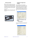
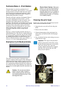
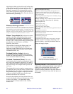
Examples of printhead problems
The white line in the center of the black stripe
suggests a number of blown pixels. The wide black
stripe means that a large number of pixels are fully on
(hot) all the time. Either of these problems may call
for a replacement printhead (but the black stripe may
be caused instead by image handling issues between
printer driver and the application that created the card
layout).
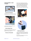
Cleaning the print head
Do this only if print quality has deteriorated and all
other corrective actions have failed.
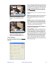
1. Open the main cover (this will raise the print
head).
2. Remove the color ribbon.
3. Wipe the bottom edge of the print head a few
times using a Q-Tip moistened with Isopropyl
alcohol.
4. Dry off with the lint free cloth, taking care not to
touch the active edge.
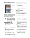
Caution • Do not touch the bottom
edge of the print head. Grease or
other contaminants from the hands
can attract particles that may in time
dameage the head.
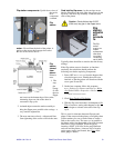
Electric Shock Caution • Make sure
power is disconnected before working
on the print head. Also note that the
head will likely be destroyed if power is
reapplied while you are in porcess of
reconnecting the cable, or if the plug
is not seated properly.
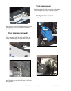
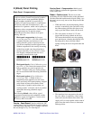
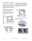
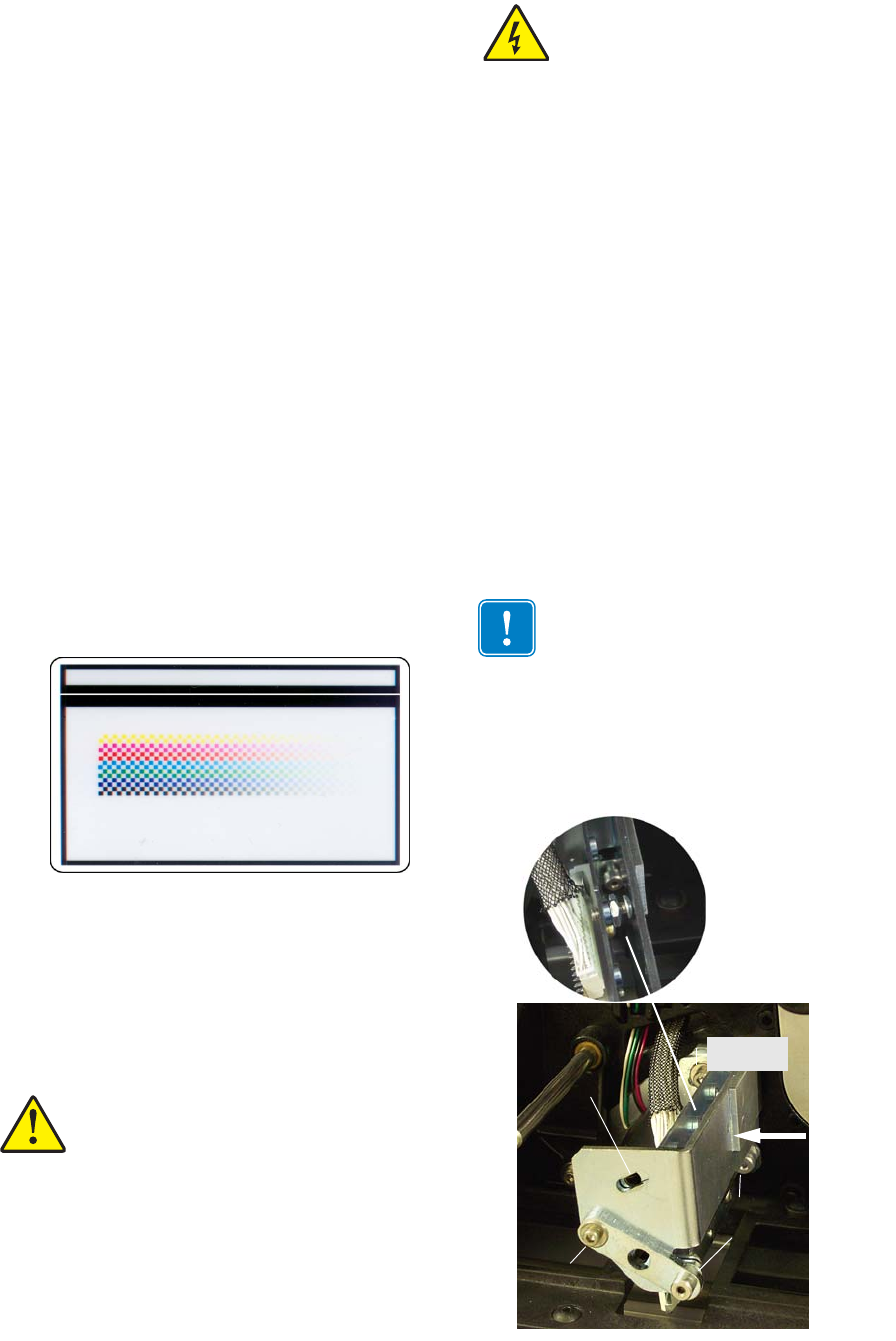
Important • The angle of the print head
relative to the surface of the card is set by
this #4-40 button head screw and lock nut
(5/64" hex wrench, 5/16" open end
wrench). Replacement heads are shipped
with theis screw preset, but some fine
tuning may be required.
#4-40 skt hd
cap screw
3
2
1
#4-40 shoul-
der screws
(5/64" hex
Not Used
Yaw adjust
(technician
only)
Access for
head
angle


