


980541-001 Rev. A P640i Card Printer User Guide 59
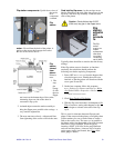
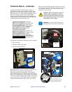
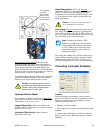
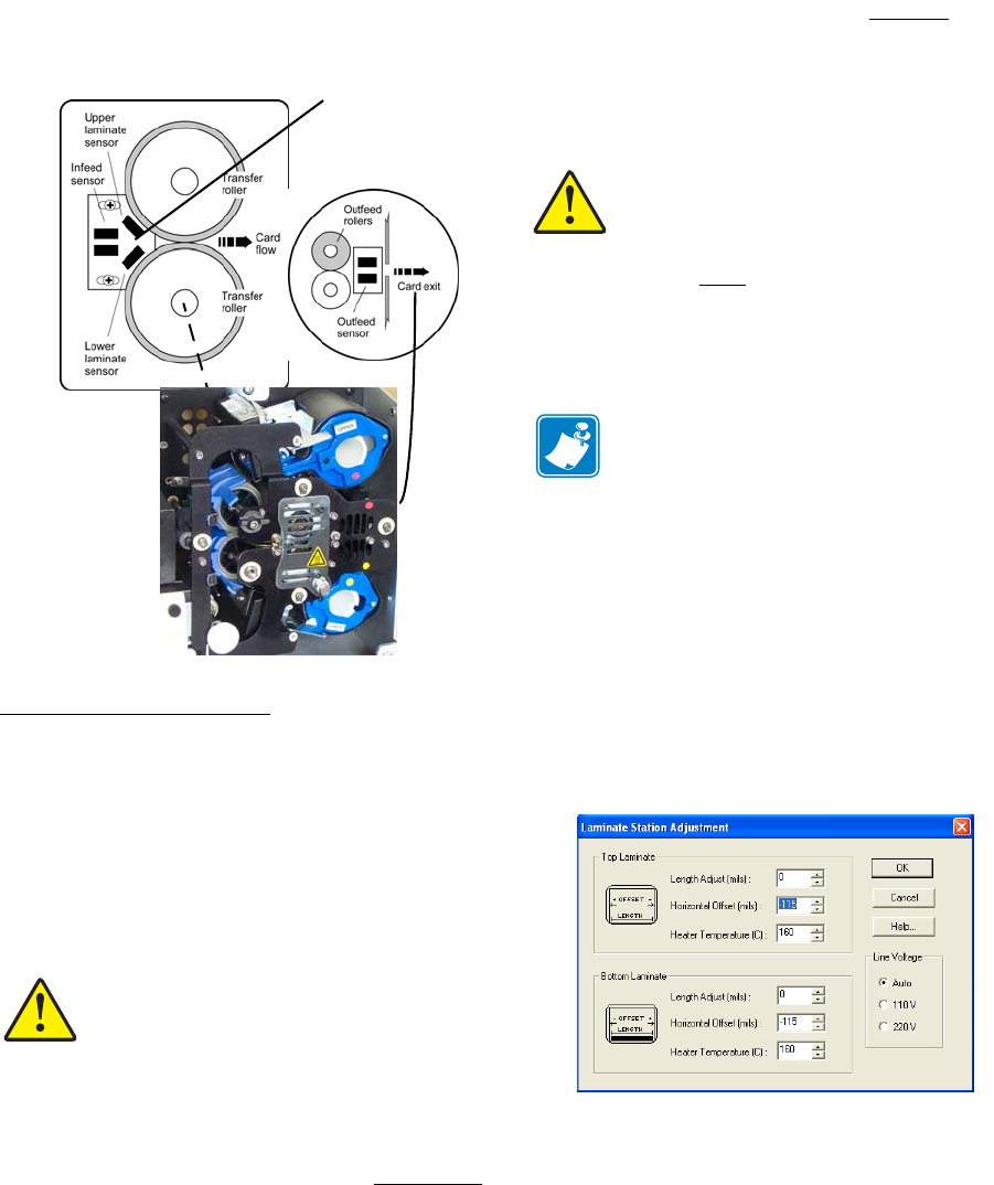
Functional test of the sensors From each of the
laminators, upper and lower, remove the transfer
guide and the laminate patch, if any, beneath it. The
sensor should read high, around 250. Replace the
guide, and the sensor should read no lower than 180. If
lower than 180, move the sensor board away from the
transfer rollers, to the left, diagram below.
Complete the test by running laminate onto the rollers
(press the LAMINATE button). The sensor should
read below 20. Adjust sensor board to correct.
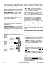
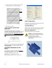
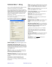
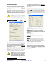
Laminate Station Adjust
Start > Printers (or Printers and Faxes) > Right click
Zebra P640i > Properties > Device Settings > Printer
Adjustment > Laminate Station Adjust
Length Adjust (mils): This is the length of the
laminate “patch”. If the patch is too long, decrease this
number, and vice versa.
Horizontal Offset (mils): Adjusts laminate
placement on the card.
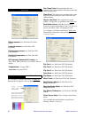
Heater Temperature : This is the set point
-
temperature desired - not the actual temperature. For
actuals, see Sensor Data, preceding page. NOTE:
Temperatures are monitored by thermocouples at the
core of the heated rollers. Surface temperatures may
differ significantly.
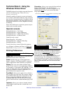
Line Voltage: If Auto is selected, the printer guesses
line voltage based on line frequency, assuming that
110V will be @ 60Hz, and 230V @ 50Hz. If this isn’t
the case in your locality, the printer will guess wrong,
and you should set the voltage manually.
This setting has nothing to do with the printer power
supply. Like the laminator heaters, the power supply
can handle any voltage from 110V to 230V, so an
incorrect setting here will cause no immediatedamage.
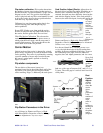
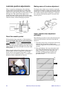
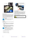
Correcting Laminator Problems
Problem
Laminate bunches up outside the cutter assembly,
having missed the feed slot. This can happen to either
upper or lower laminates. It is probably a cassette
installation problem, such as:
1. Failing to latch the cassette
2. Out-of-square scissor cut on the leading edge of the
laminate
3. Leading edge of laminate not reeled in even with
the lips of the cassette. Reference Section 2, Media
Handling.
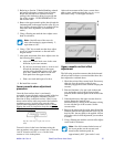
Caution • The sensor board must be
symmetrically positioned relative to the
transfer rollers. with its attachement
screws central in their slots.
Caution • Do not set the temperature ABOVE
180°C, or BELOW room temperature
Note • Running the printer at 220V,
60Hz in Auto mode may cause premature
failure ofthe heaters. Running the printer
at 110V, 50Hz in Auto mode may cause
abnormally long heat-up time and poor
temperature control.
It is possible to
get a false
“good” reading
if the sensors
are too close to
the feed rollers.