


980541-001 Rev. A P640i Card Printer User Guide 45
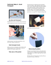
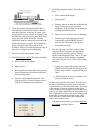
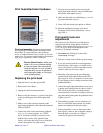
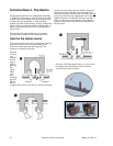
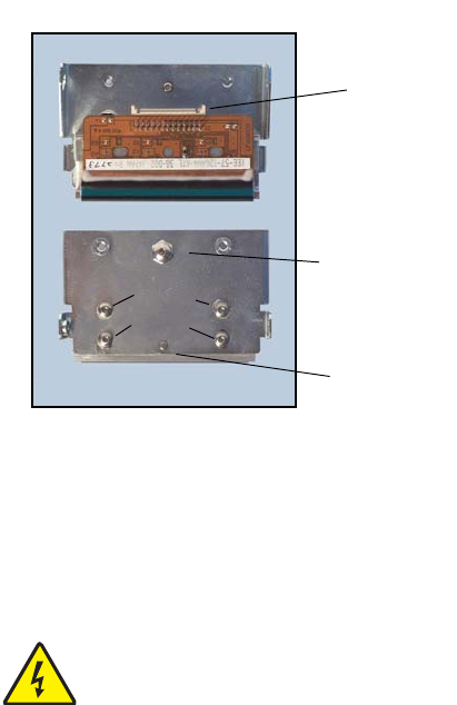
Print head attachment hardware
Print head assembly : Replacement print heads
are shipped pre-assembled to the mounting bracket
shown here. To ensure uniform contact pressure
across its width, the head is free to rotate ± 2° about its
center pivot. It is secured to the bracket by four button
head screws, tightened to allow a sliding fit.
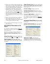
Replacing the print head
1. Open the main cover, then power OFF.
2. Remove the color ribbon.
3. Unplug the cable from the print head.
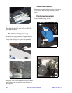
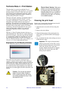
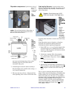
4. Remove only the fasteners
1, 2, and 3 in the photo
on the preceding page, then lift the print head
clear.
5. Make a note of the resistance entered on the
replacement printhead’s label (should be between
2400 and 3600 Ù.
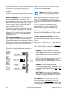
6. Connect the cable to the replacement printhead,
making sure it is seated properly, see “STOP”
above. Install the print head, securing it with
shoulder bolts
1 and 2, fully tightened, then
loosely with socket head cap screw
3 (with plain
washer) through the slot in the bracket.
7. Pivot the head assembly forward to bring the
angle adjust button head in contact with the print
head frame, then tighten screw
3.
8. Make sure the cable is not inhibiting
free rotation of
the print head about its pivot.
9. Power ON, then check print quality as follows.
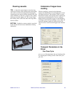
10. Enter the printhead resistance in the driver
Properties “Print Station Adjustment” screen,
page TN4-4.
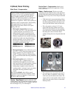
Print quality tests and
adjustments
The objective in the following is to find the best
compromise between image quality and ribbon
wrinkling. In the printer driver go to Printing Preferences
> Image Adjustment
, then set both Brightness and
Contrast to 50 (default condition).
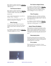
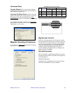
1. Run
IDPrint Lite, Tech Note 8, then select
Graytone.bmp as Image 1.
2. Print two or three cards with the graytone image.
3. If you are satisfied with the overall appearance
and uniformity of the image, you might wish to
leave well alone. If you feel some improvement
could be achieved, proceed to Step 4.
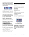
4. Referring to the photo on the preceding page,
mark the head-angle-adjust button head with a
fiber tip pen to serve as a reference. Loosen screw
#3 just enough to allow sliding movement of the
printhead bracket.
5. Unlock the angle adjust button head screw, turn it
a quarter-turn counterclockwise, then re-lock it.
This will have the effect of rotating the head
counterclockwise a fraction of a degree when you
snug the button head against the printhead frame.
Tighten screw #3.
6. Print another graytone card for comparison. If
there is a noticeable improvement, try another
quarter-turn adjustment, then print again.
7. If the print quality is seen to deteriorate rather
than improve, return to the as-shipped setting of
the head angle screw, then try rotating it
clockwise in quarter-turn increments.
Electric Shock Caution • Make sure
power is disconnected before working
on the print head. Also note that the
head will likely be destroyed if power is
reapplied while you are in porcess of
reconnecting the cable, or if the plug
is not seated properly.
Connector
Head
angle
adjust
Print
head
pivot
Do NOT
tighten these