


52 P640i Card Printer User Guide 980541-001 Rev. A
If you detect that either of the arms catches at one end
of the platen, but is free at the other, the carrier needs
Azimuth adjustment, see below. Always correct for
azimuth error before adjusting the gap between arms
and platen.
If there is no azimuth error, but insufficient clearance
between arms and platen, see
Gap adjustment below.
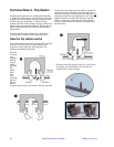
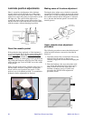
Azimuth adjustment: The flip station carrier is
held in alignment with the platen by a U-shape
molding that rides along a fixed rail in the motor
housing behind the carrier. Using a fiber tip pen mark
the screw for reference, then adjust it in very small
increments, such as 1/8 of a turn. A full turn of the
screw moves the U-shape molding about 0.08" (2
mm), rotating the carrier almost 3º.
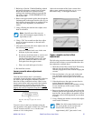
To fine tune the azimuth adjustment, run Flip Test 3
with flip
selected. If the gap between the rear flipper
arm and the platen is to spec (0.004") at the arm’s
mid-point, and if neither end of the arm snags after
repeated flip cycles, you can be sure the azimuth
adjustment is good.
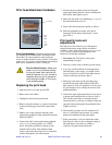
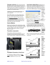
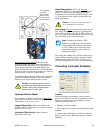
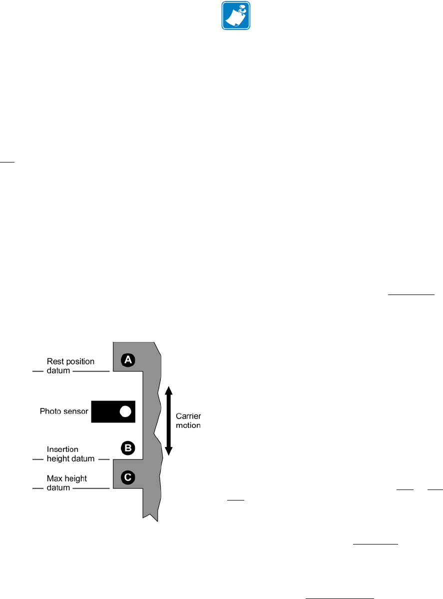
Flip carrier sensor tabs: This view is from left to
right, along the center wall of the printer ockwise
rotation of the azimuth adjust screw causes clockwise
rotation of the carrier assembly, viewed from above.
Example: if the platen tugs down the right hand end of
front flipper arm as the carrier elevates, the carrier
needs clockwise rotation.
Gap adjustment: The flipper arms must be
separated so that they clear the platen, but not so far
that they
lose their
grip on
the card.
There is
a fine
line
between
too tight
(grabbin
g the
platen)
and too
loose
(failing
to hold
the card
securely)
.
Because it is easily accessible, and doesn’t require
removal of the rear cover, try to correct the problem
with the front flipper adjustment.
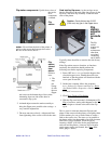
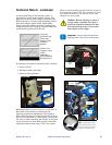
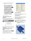
Mark the bushing for reference with a fiber tip pen.
Using a ¼" open end wrench, adjust in
very small
increments
, such as 1/8 of a turn. A full clockwise turn
of the screw moves the bushing in by about 0.03” (¾
mm).
If you are starting from scratch, set the nose of
bushing about 0.02" (½ mm) proud of the inner
surface of the carrier. You can estimate this by
comparison with a CR-80 card, which is 0.03" thick.
After adjusting the gap: Check operation of the
flip station by running
Flip Test 3 with Flip, both with
and without a card in the flipper arms.
The rear flipper arm is different: You need to
remove the rear cover for access. Also, it’s not
possible to adjust the bushing without first removing
the cam.
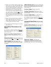
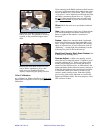
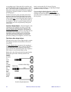
Flip Station Routines in the Driver
Start > Printers (or Printers and Faxes) > Right click
Zebra P640i > Properties > Device Settings > Control
> Advanced Utilites
Flip Test 1: Picks up a card, runs it to the flip
station, flips it, raises it to the laminator infeed, then
ejects it through the laminator. The sequence repeats
until the PRINT button is pressed and released.
Flip Test 2: Picks up a card, runs it to the flip
station, flips it, returns it to the platen, then backs it
out to the card sensor (by the mag head). The
sequence repeats until the PRINT button is pressed
and released.
Flip Test 3: See Flip Station Adjustment
Procedure, preceding page. Exercises the flip station
by raising and lowering the flip station carrier, one
cycle per click. The radio buttons select Flip
or No
Flip cycles.
Eject Card: Picks up a card, runs it to the flip
station, raises it to the laminator infeed, then ejects
it through the laminator. Like Flip Test 1
, but done
once only, and without flipping.
Flip/Pause: Picks up a card, runs it to the flip
station, raises it to the laminator infeed, then holds this
position (termed the Insertion Height
in the flip
station dialog) until the user presses the PRINT button
(at which point the flip carrier descends, and the truck
returns the card to the hopper).
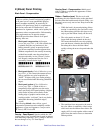
Note • Inserting a CR-80 card into the
flipper arms to check for grip is easier if
you remove the color ribbon.