


13-9
Cisco ASA 5500 Series Configuration Guide using ASDM
Chapter 13 Starting Interface Configuration (ASA 5505)
Starting ASA 5505 Interface Configuration
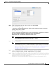
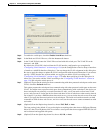
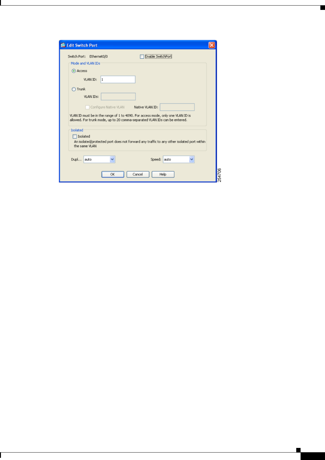
Step 4 To enable the switch port, check the Enable SwitchPort check box.
Step 5 In the Mode and VLAN IDs area, click the Access radio button.
Step 6 In the VLAN ID field, enter the VLAN ID associated with this switch port. The VLAN ID can be
between 1 and 4090.
By default, the VLAN ID is derived from the VLAN interface configuration you completed in
“Configuring VLAN Interfaces” section on page 13-6 (on the Configuration > Device Setup > Interfaces
> Interfaces > Add/Edit Interface dialog box). You can change the VLAN assignment in this dialog box.
Be sure to apply the change to update the VLAN configuration with the new information. If you want to
specify a VLAN that has not yet been added, we suggest you add the VLAN according to the
“Configuring VLAN Interfaces” section on page 13-6 rather than specifying it in this dialog box; in
either case, you need to add the VLAN according to the “Configuring VLAN Interfaces” section on
page 13-6 and assign the switch port to it.
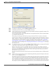
Step 7 (Optional) To prevent the switch port from communicating with other protected switch ports on the same
VLAN, check the Isolated check box.
This option prevents the switch port from communicating with other protected switch ports on the same
VLAN. You might want to prevent switch ports from communicating with each other if the devices on
those switch ports are primarily accessed from other VLANs, you do not need to allow intra-VLAN
access, and you want to isolate the devices from each other in case of infection or other security breach.
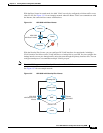
For example, if you have a DMZ that hosts three web servers, you can isolate the web servers from each
other if you apply the Protected option to each switch port. The inside and outside networks can both
communicate with all three web servers, and vice versa, but the web servers cannot communicate with
each other.
Step 8 (Optional) From the Duplex drop-down list, choose Full, Half, or Auto.
The Auto setting is the default. If you set the duplex to anything other than Auto on PoE ports Ethernet
0/6 or 0/7, then Cisco IP phones and Cisco wireless access points that do not support IEEE 802.3af will
not be detected and supplied with power.
Step 9 (Optional) From the Speed drop-down list, choose 10, 100, or Auto.