


7-7
Cisco ASR 1001-X Router Hardware Installation Guide
OL-32376-02
Chapter 7 Removing and Replacing FRUs from the Cisco ASR 1001-X Router
Removing and Replacing the Cisco ASR 1001-X Router Power Supplies
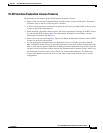
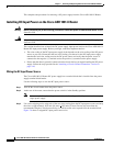
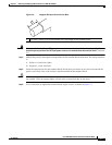
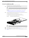
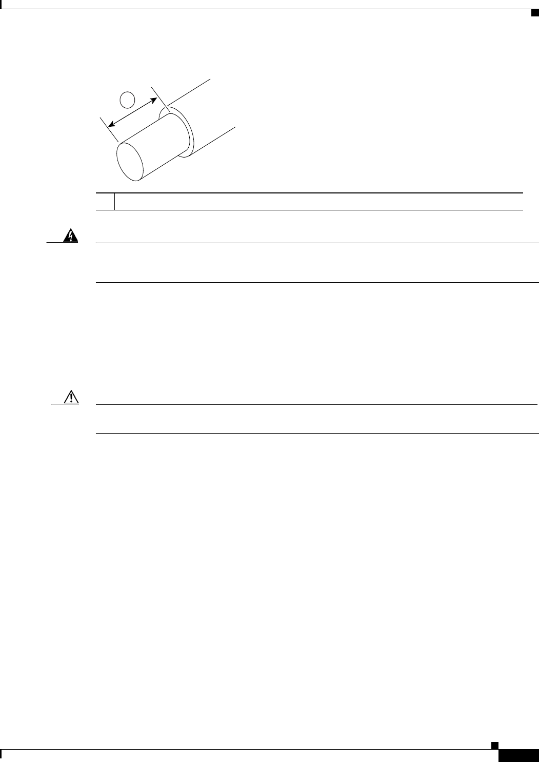
Figure 7-6 Stripped DC Input Power Source Wire
Warning
An exposed wire lead from a DC input power source can conduct harmful levels of electricity. Be sure
that no exposed portion of the DC input power source wire extends from the terminal block.
Statement
122
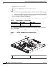
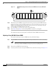
Step 4 Identify the positive and negative feed positions for the terminal block connection. The wiring sequence
is:
1. Positive (+) lead wire (right)
2. Negative (–) lead wire (left)
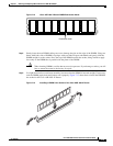
Step 5 Insert the exposed wire into the terminal block. Ensure that you cannot see any wire lead outside the
plastic cover. Only wires with insulation should extend from the terminal block.
Caution Do not overtorque the terminal block captive screws. Ensure that the connection is snug, but the wire is
not crushed. Verify by tugging lightly on each wire to ensure that they do not move.
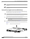
Step 6 Use a screwdriver to tighten the terminal block captive screws, as shown in Figure 7-7.
1 0.39 inch (10 mm) is the recommended wire-strip length for the terminal block.
57019
1