


7-10
Cisco ASR 1001-X Router Hardware Installation Guide
OL-32376-02
Chapter 7 Removing and Replacing FRUs from the Cisco ASR 1001-X Router
Removing and Replacing the Cisco ASR 1001-X Router DIMM
• Back up the data that you want to save.
• Remove the power supplies before you remove the chassis top cover.
Caution The top cover cannot be removed until the power supplies are removed from the chassis. The
chassis has a safety mechanism built in to prevent the removal of the top cover until the power
supplies are removed.
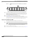
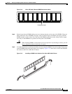
• The DIMM component is keyed and slotted for easier connection.
• The Cisco ASR 1001-X Router has two DIMM slots.
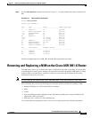
Table 7-1 shows the slots that are supported for inserting the memory DIMMs in the Cisco ASR1001-X
Router.
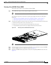
This section describes how to remove the chassis cover and then remove and replace the Cisco ASR
1001-X Router DIMMs.
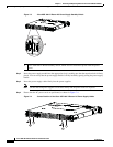
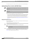
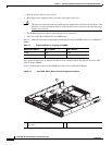
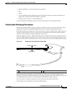
Figure 7-9 shows the location of the DIMM slots in the Cisco ASR 1001-X Router.
Figure 7-9 Cisco ASR 1001-X Router Internal Component Location
Table 7-1 Supported Slots for Inserting the DIMMs
Memory PID Option Slot 0 (U101D) Slot 1 (U103D)
U1D0 4 GB 4 GB
U1D1 8 GB 8 GB
1 Cisco ASR 1001-X Router DIMM location
(two slots)
1
371134