


1-4
Cisco ASR 1001-X Router Hardware Installation Guide
OL-32376-02
Chapter 1 Cisco ASR 1001-X Router Overview
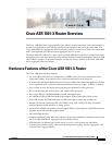
Hardware Features of the Cisco ASR 1001-X Router
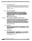
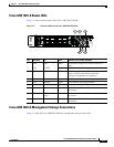
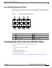
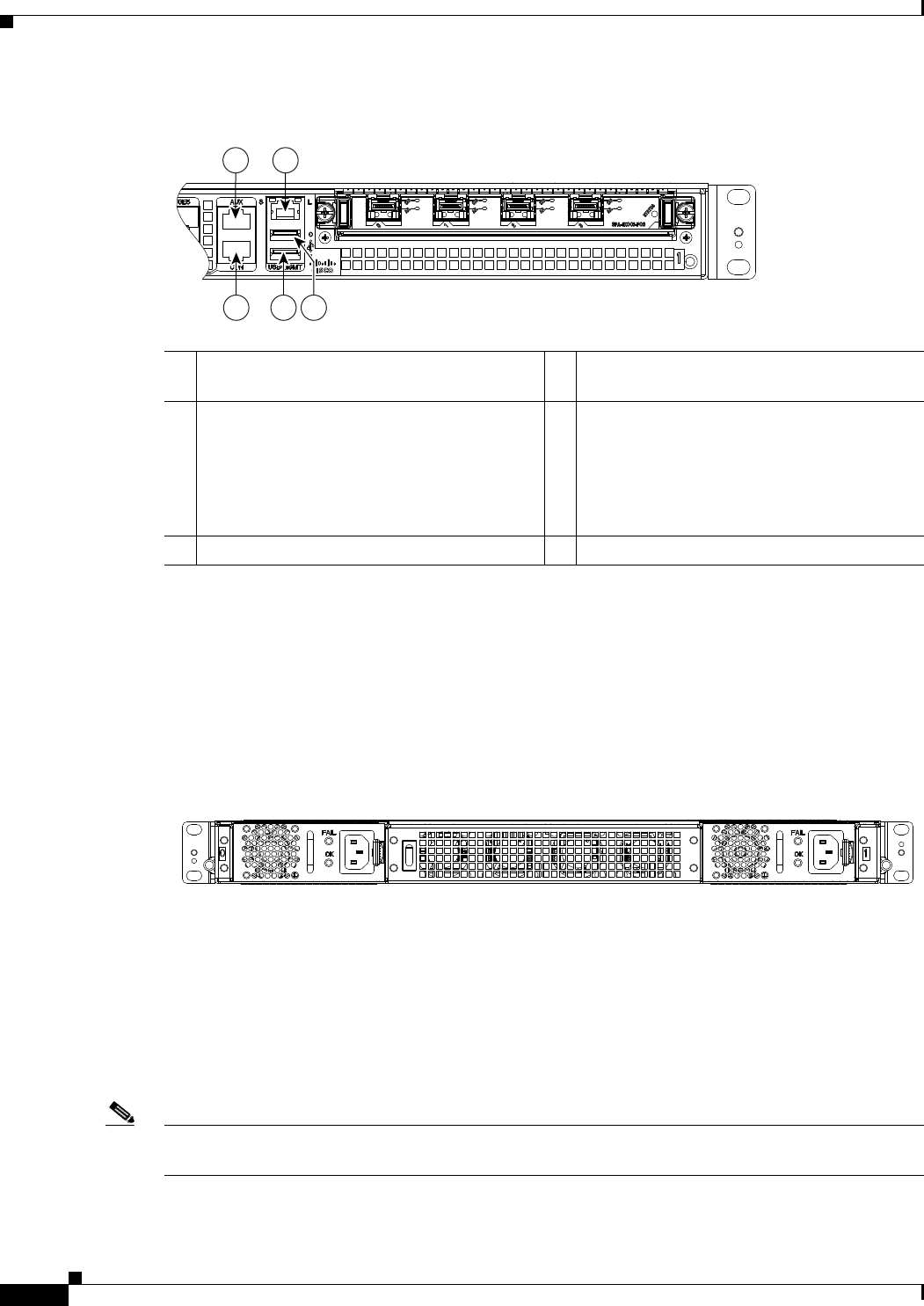
Figure 1-3 Management Storage Connections for the Cisco ASR 1001-X Router
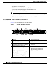
Cisco ASR 1001-X Chassis Rear View
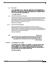
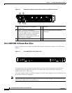
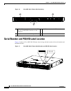
Figure 1-4 shows the rear of the Cisco ASR 1001-X Router with four fans and two AC or DC power
supplies.
Figure 1-4 Cisco ASR 1001-X Router Rear View
Four internal fans draw cooling air into the chassis and across internal components to maintain an
acceptable operating temperature. The fans are located in the center of the chassis. The fans are
numbered from 0 to 3, right to left.
Two power supplies, either two AC power supplies or two DC power supplies are accessed from the rear
of the router and are hot-swappable.
Note The Cisco ASR 1001-X Router can support two AC or two DC power supplies. Do not install mixed AC
and DC power supply units in the same chassis.
1 AUX—One RJ-45/RS-232 compatible
auxiliary port.
4 USB port 1
2 MGMT —one RJ-45 10/100/1000
management Ethernet port. The Management
Port has two LEDs, L and S. L green indicates
Link operations. S blinks the negotiated
Ethernet speed (1 blink 10 Mbps, 2 blinks 100
Mbps, 3 blinks, 1 000 Mbps).
5 CON—One RJ-45/RS-232 compatible
console port
3 USB port 0 —
1 2
3
5 4
371078
371076