


4-13
Cisco ASR 1001-X Router Hardware Installation Guide
OL-32376-02
Chapter 4 Cisco ASR 1001-X Router Installation
Connecting Cables
A crossover cable reverses pin connections from one end to the other. In other words, it connects pin 1
(at one end) to pin 8 (at the other end), pin 2 to pin 7, pin 3 to pin 6, and so on. You can identify a
crossover cable by comparing the two modular ends of the cable. Hold the cable ends in your hand,
side-by-side, with the tabs at the back. Ensure that the wire connected to the outside (left) pin of the left
plug (pin 1) is the same color as the wire connected to the outside (right) pin of the right plug (pin 8).
Caution Both the console and auxiliary ports are asynchronous serial ports; devices connected to these ports must
be capable of asynchronous transmission. To meet Class A emissions requirements, shielded cables must
be used for the console and auxiliary port connectors.
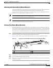
Before connecting to the console interface on the router using a terminal or PC, perform the following
steps:
Step 1 Before connecting a terminal to the console port, configure the terminal to match the chassis console
port as follows: 9600 baud, 8 data bits, no parity, 1 stop bits (9600 8N1).
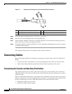
Step 2 Connect one end of the RJ-45 cable to the serial RJ-45 console port (CON) on the Cisco ASR 1000-X
Router using the RJ-45 to DB-9 cable. Connect the DB-9 end to your terminal equipment.
Note For information about how to change the default settings to meet the requirements of your terminal or
host, see the Cisco IOS Terminal Services Configuration Guide.
Step 3 After you establish normal router operation, you can disconnect the terminal.
Use the following procedure to connect a video terminal to the console port.
Step 4 Go to the “Connecting to the Mini USB Console Port” section on page 4-13 to continue the installation.
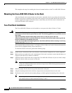
Connecting to the Mini USB Console Port
The USB serial console port connects directly to the USB connector of a PC using a USB Type A to 5-pin
mini USB Type-B cable. The USB Console supports full speed (12Mbps) operation. The console port
does not support hardware flow control.
Note • Always use shielded USB cables with a properly terminated shield. The USB serial console interface
cable must not exceed 3 meters in length.
• Only one console port can be active at a time. When a cable is plugged into the USB console port,
the RJ-45 port becomes inactive. Conversely, when the USB cable is removed from the USB port,
the RJ-45 port becomes active.
• 4-pin mini USB Type-B connectors are easily confused with 5-pin mini USB Type-B connectors.
Note that only the 5-pin mini USB Type-B is supported.
The default parameters for the console port are 9600 baud, 8 data bits, no parity, and 1 stop bit.
For operation with a Microsoft Windows OS version older than Windows 7, the Cisco Windows USB
Console Driver must be installed on any PC connected to the console port. If the driver is not installed,
prompts guide you through a simple installation process.
The Cisco Windows USB Console Driver allows plugging and unplugging the USB cable from the
console port without affecting Windows HyperTerminal operations. No special drivers are needed for
Mac OS X or Linux.