


1-3
Cisco ASR 1001-X Router Hardware Installation Guide
OL-32376-02
Chapter 1 Cisco ASR 1001-X Router Overview
Hardware Features of the Cisco ASR 1001-X Router
Cisco ASR 1001-X Router LEDs
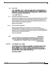
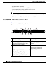
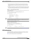
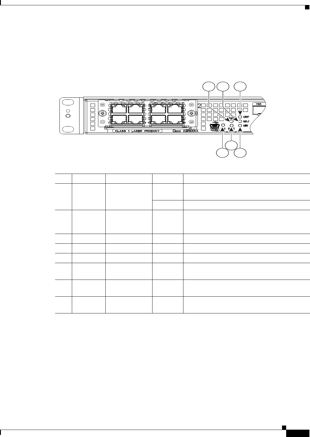
Figure 1-2 shows the front panel of the Cisco ASR 1001-X Router.
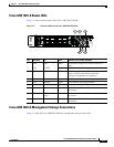
Figure 1-2 Common LEDs for the Cisco ASR 1001-X Router
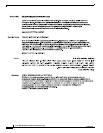
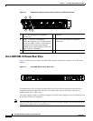
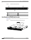
Cisco ASR 1001-X Management Storage Connections
Figure 1-3 show the Cisco ASR1001-X Router’s management storage connections.
371077
3
21
46
5
No. LED Label LED Color Behavior in the Power-Up State
1 PWR Power Green All the power supplies are within operational
limits.
2 MAJ MAJOR Red Major alarm indicator.
3 CRIT CRITICAL Red Critical alarm indicator. Will be off when the
router is initially powered up and all the
configured components are available.
4 MIN MINOR Amber Minor alarm indicator
5 STAT STATUS Green Cisco IOS has successfully booted.
Yellow The system is at ROMMON.
Red System failure. Will be off when the router is
powered up.
6 EN USB Console
Enable
Green Indicates that the mini eUSB connector is used as
the console.
Off Indicates that the RJ-45 connector is being used as
the console.