


5-18
Cisco ASR 1001-X Router Hardware Installation Guide
OL-32376-02
Chapter 5 Cisco ASR 1001-X Router Power Up and Initial Configuration
Environmental Monitoring and Reporting Functions
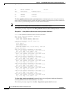
------ ------ -------- -------------------
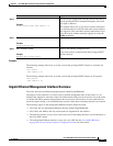
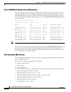
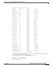
xcvr container 0/0/1 Apr 22 2014 15:25:57 CRITICAL Transceiver Missing -
Link Down [1]
Temp: Inlet R0/30 Apr 22 2014 15:30:37 CRITICAL Temp Above Normal (Shutdown)
[1]
GigabitEthernet0 Apr 22 2014 15:25:42 INFO Physical Port Administrative
State Down [2]
Router#
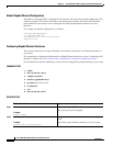
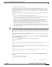
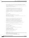
Fan Failures
Four internal fans draw cooling air into the chassis and across internal components to maintain an
acceptable operating temperature. The fans are located in the center of the chassis. The fans are
numbered from 0 to 3, right to left. When the system power is on, all fans should be operational.
However, the system continues to operate even if a fan fails.
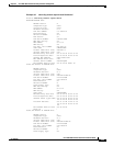
Use the show platform hardware slot <slot> fan status command to view the status of the fans, for
example:
Router# show platform hardware slot P2 fan status
Fan group 1 speed: 60%
Fan 0: Normal
Fan 1: Normal
Fan 2: Normal
Fan 3: Fail
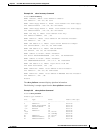
Reporting Functions
The chassis manager on the forwarding engine control processor manages the local resources of the
forwarding processor. The Cisco ASR 1001-X Router displays warning messages on the console if the
chassis interface-monitored parameters exceed a threshold. You can also retrieve and display
environmental status reports with the following commands:
• show environment all
• show version
• show inventory
• show platform
• show platform software status control-processor
• show diag
Parameters are measured and reporting functions are updated every 60 seconds. A brief description of
each of these commands follows.
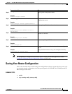
The show environment all command displays temperature, voltage, fan, and power supply information.
The following is sample output from the show environment all command.
Example 5-2 show environment all Command
Router# show environment all