


RESTRICTED USE ONLY Fargo Electronics, Inc.
DTC500 Series Card Printer/Encoders User Guide (Rev. 6.0)
285
Replacing the plastic Printer casing
Step Procedure
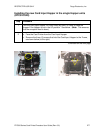
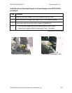
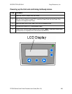
1 Plug the LCD control panel in to J18 of the Main Circuit Board.
2 Replace the ground strap onto the Spade connector above the Power Supply
casing.
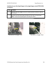
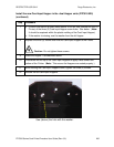
3 Confirm that wires are still firmly routed through the Cover.
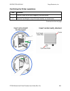
4 On the Main Cover, open the Card Input Hopper Door to allow for clearance.
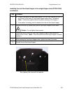
5 Set the casing back onto Printer.
6 Confirm that all wires are inside the casing.
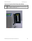
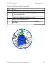
7 Press the Cover down until the four (4) corner latches are secure.
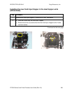
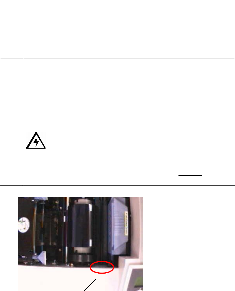
8 Replace the two (2) screws that hold the casing on the Frame.
a. Place the screws into the holes and partially tighten them.
Caution: Do not tighten them completely.
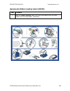
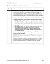
b. Align the top edge of the casing with the edge of the Printer side plate.
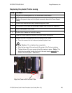
c. Tighten the two (2) cover screws to hold the casing in place. (Note: This
should be done while holding the front of the main casing even with the
Printer's front side plate. See below.)
Align the Cover with the Side Plate.