


RESTRICTED USE ONLY FARGO Electronic, Inc.
DTC500 Series Card Printer/Encoders User Guide (Rev. 6.0)
ix
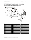
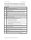
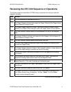
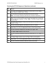
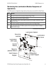
Reviewing the DTC 520 Sequence of Operations
The following sequence describes a DTC525 doing a dual sided full color print job with
magnetic encoding.
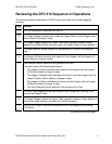
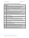
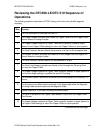
Step
Process
1 The File information is received from the PC.
2 The Flipper Stepper activates and rotates the Flipper Table until the Flipper Home
Sensor detects a change in state.
3 The Flipper Stepper rotates the Flipper Table back a specific number of steps
(based on the Flipper Offset setting) to return the Flipper Table to a level position.
4 The Card Detection Sensor detects for the presence of a Card in the exception
feed.
5 The Hopper Lift Motor activates and lowers the Card Hopper until the Hopper Lift
Sensor detects a change in state.
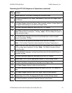
6 The Card Detection Sensor detects the presence of a Card.
7 The Card Feed Stepper activates and feeds a card through the Cleaning Roller
and onto the Flipper Table.
8 The Flipper Stepper rotates the Flipper Table a specific number of steps (based on
the Encoder Angle setting) to position the card for Encoding.
9 The Encoder/Flipper Feed Motor activates until the Card passes the Encoding
TOF Sensor.
10 The Encoding Feed Motor feeds the Card back to the Flipper Table while the
Magnetic Encoding Head transfers data onto the Magnetic Stripe.
11 Repeat Steps 9 to 10 for each Encoding and Verification pass.
12 The Card is centered on the Flipper Table based on input from the Flipper Table
Card Sensor.
14 The Card Feed Motor feeds the Card to the Print TOF Sensor.
15 The Ribbon Drives turn ON and move until the correct panel is detected by the
Print Ribbon Sensor Array (5 reflective). All Stop. (Note: The Print Ribbon
Encoder is active during this step.)
Continued on the next page