


Clock Module
MCF52211 ColdFire® Integrated Microcontroller Reference Manual, Rev. 2
6-22 Freescale Semiconductor
6.8.4.8 Loss of Clock Detection
The LOCEN bit in the SYNCR enables the loss of clock detection circuit to monitor the input clocks to
the phase and frequency detector (PFD). When the reference or feedback clock frequency falls below the
minimum frequency, the loss of clock circuit sets the sticky LOCS flag in the SYNSR.
NOTE
In external clock mode, the loss of clock circuit is disabled.
6.8.4.9 Loss of Clock Reset
The clock module can assert a reset when a loss of clock or loss of lock occurs. When a loss-of-clock
condition is recognized, reset is asserted if the LOCRE bit in SYNCR is set. The LOCS bit in SYNSR is
cleared after reset. Therefore, the LOC bit must be read in RSR to determine that a loss of clock condition
occurred. LOCRE has no effect in external clock mode.
To exit reset in PLL mode, the reference must be present, and the PLL must acquire lock.
Reset initializes the clock module registers to a known startup state as described in Section 6.7, “Memory
Map and Registers.”
6.8.4.10 Alternate Clock Selection
Depending on which clock source fails, the loss-of-clock circuit switches the system clocks source to the
remaining operational clock. The alternate clock source generates the system clocks until reset is asserted.
As Table 6-18 shows, if the reference fails, the PLL goes out of lock and into self-clocked mode (SCM).
The PLL remains in SCM until the next reset. When the PLL is operating in SCM, the system frequency
depends on the value in the RFD field. The SCM system frequency stated in electrical specifications
assumes that the RFD has been programmed to binary 000. If the loss-of-clock condition is due to PLL
failure, the PLL reference becomes the system clocks source until the next reset, even if the PLL regains
and relocks.
A special loss-of-clock condition occurs when the reference and the PLL fail. The failures may be
simultaneous, or the PLL may fail first. In either case, the reference clock failure takes priority and the
PLL attempts to operate in SCM. If successful, the PLL remains in SCM until the next reset. If the PLL
cannot operate in SCM, the system remains static until the next reset. The reference and the PLL must be
functioning properly to exit reset.
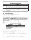
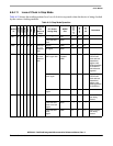
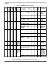
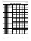
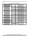
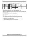
Table 6-18. Loss of Clock Summary
Clock
Mode
System Clock Source
Before Failure
Reference Failure Alternate Clock
Selected by LOC Circuit
1
Until Reset
1
The LOC circuit monitors the reference and feedback inputs to the PFD. See Figure 6-12.
PLL Failure Alternate Clock
Selected by LOC Circuit Until Reset
PLL PLL PLL self-clocked mode PLL reference
External External clock None NA