


Queued Serial Peripheral Interface (QSPI)
MCF52211 ColdFire® Integrated Microcontroller Reference Manual, Rev. 2
Freescale Semiconductor 23-5
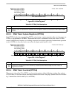
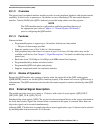
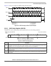
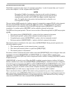
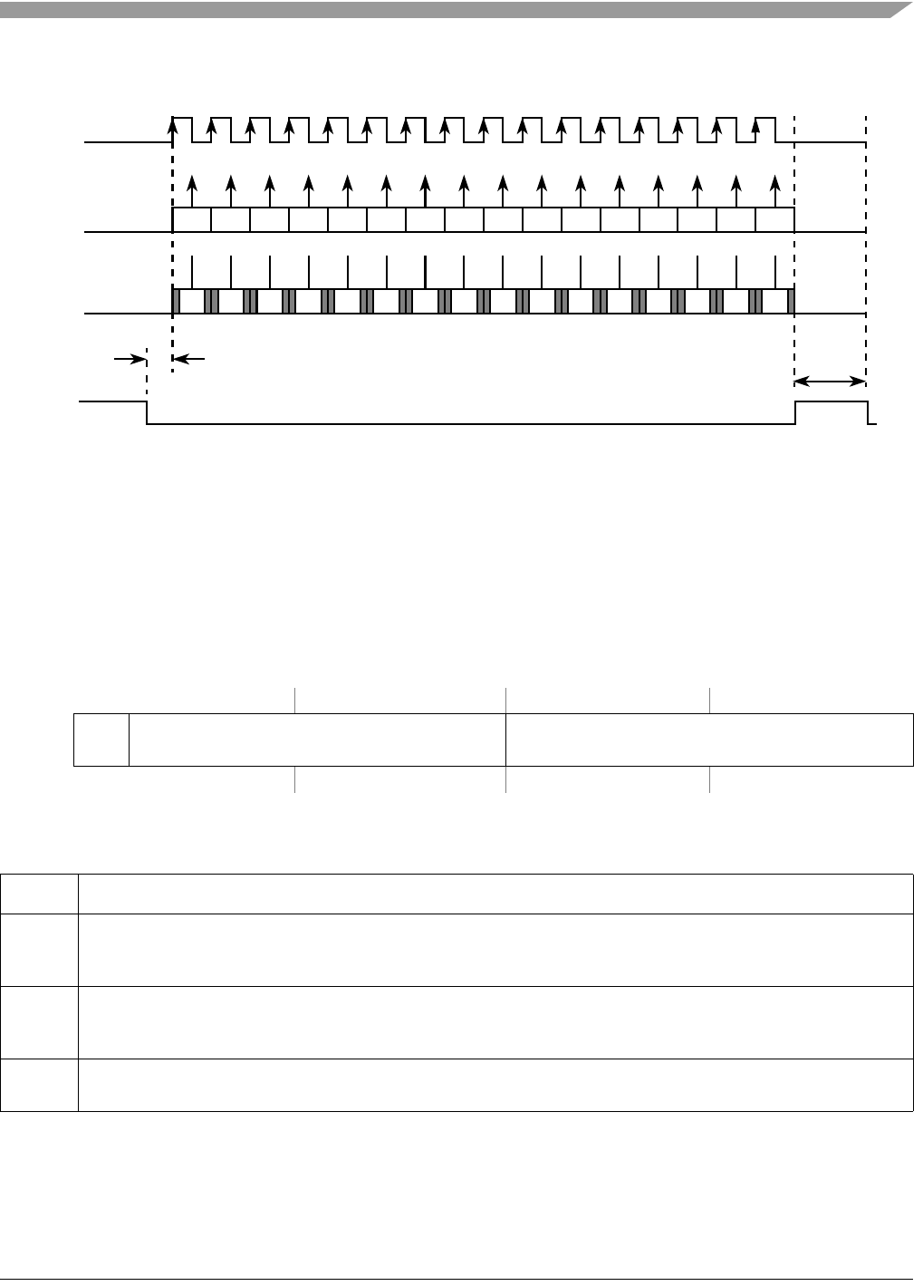
Figure 23-3 shows an example of a QSPI clocking and data transfer.
Figure 23-3. QSPI Clocking and Data Transfer Example
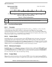
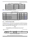
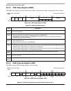
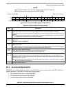
23.3.2 QSPI Delay Register (QDLYR)
The QDLYR is used to initiate master mode transfers and to set various delay parameters.
IPSBAR
Offset:
0x00_0344 (QDLYR) Access: User read/write
1514131211109876543210
R
SPE QCD DTL
W
Reset0 0 00010000000100
Figure 23-4. QSPI Delay Register (QDLYR)
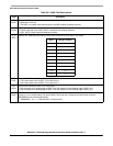
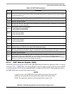
Table 23-4. QDLYR Field Descriptions
Field Description
15
SPE
QSPI enable. When set, the QSPI initiates transfers in master mode by executing commands in the command RAM.
Automatically cleared by the QSPI when a transfer completes. The user can also clear this bit to abort transfer unless
QIR[ABRTL] is set. The recommended method for aborting transfers is to set QWR[HALT].
14–8
QCD
QSPI_CLK delay. When the DSCK bit in the command RAM is set this field determines the length of the delay from
assertion of the chip selects to valid QSPI_CLK transition. See Section 23.4.3, “Transfer Delays” for information on
setting this bit field.
7–0
DTL
Delay after transfer. When the DT bit in the command RAM is set this field determines the length of delay after the
serial transfer.
QSPI_CLK
QSPI_DOUT
QSPI_DIN
QSPI_CS
A
B
QMR[CPOL] = 0
QMR[CPHA] = 1
QCR[CONT] = 0
Chip selects are active low
A=QDLYR[QCD]
B=QDLYR[DTL]
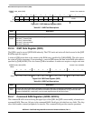
15 14 13 12 11 10 9 8 7 6 5 4 3 2 1 0
15 14 13 12 11 10 9 8 7 6 5 4 3 2 1 0
msb