


Clock Module
MCF52211 ColdFire® Integrated Microcontroller Reference Manual, Rev. 2
Freescale Semiconductor 6-27
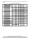
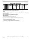
SCM 1 0 0 On On 1 — — SCM 0 0 1
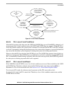
Lose reference
clock
SCM
Note:
PLL = PLL enabled during STOP mode. PLL = On when STPMD[1:0] = 00 or 01
OSC = oscillator enabled during STOP mode. Oscillator is on when STPMD[1:0] = 00, 01, or 10
MODES
NRM = normal PLL crystal clock reference or normal PLL external reference mode. During normal external reference mode,
the oscillator is never enabled. Therefore, during these modes, refer to the OSC = On case regardless of STPMD values.
EXT = external clock mode
REF = PLL reference mode due to losing PLL clock or lock from NRM mode
SCM = PLL self-clocked mode due to losing reference clock from NRM mode
RESET = immediate reset
LOCKS
‘LK -= expecting previous value of LOCKS before entering stop
0–>‘LK = current value is 0 until lock is regained which then is the previous value before entering stop
0–> = current value is 0 until lock is regained but lock is never expected to regain
LOCS
‘LC = expecting previous value of LOCS before entering stop
1–>‘LC = current value is 1 until clock is regained which then is the previous value before entering stop
1–> = current value is 1 until clock is regained but CLK is never expected to regain
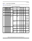
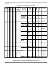
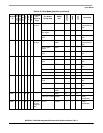
Table 6-19. Stop Mode Operation (continued)
MODE
In
LOCEN
LOCRE
LOLRE
PLL
OSC
FWKUP
Expected
PLL
Action at
Stop
PLL Action
During Stop
MODE
Out
LOCKSS
LOCK
LOCS
Comments