


UART Modules
MCF52211 ColdFire® Integrated Microcontroller Reference Manual, Rev. 2
24-18 Freescale Semiconductor
Using a 66-MHz internal bus clock and letting baud rate equal 9600, then
Eqn. 24-2
Therefore, UBG1n equals 0x00 and UBG2n equals 0xD6.
24.4.1.2.2 External Clock
An external source clock (DTINn) passes through a divide-by-1 or 16 prescaler. If f
extc
is the external clock
frequency, baud rate can be described with this equation:
Eqn. 24-3
24.4.2 Transmitter and Receiver Operating Modes
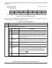
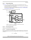
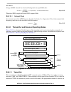
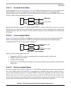
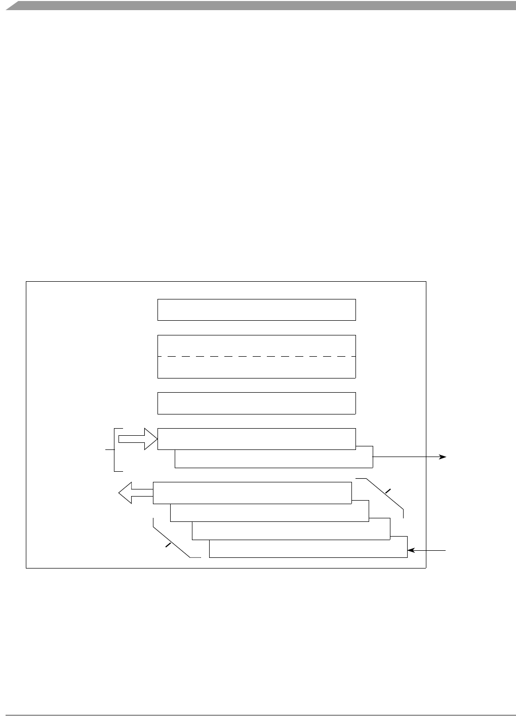
Figure 24-18 is a functional block diagram of the transmitter and receiver showing the command and
operating registers, which are described generally in the following sections. For detailed descriptions, refer
to Section 24.3, “Memory Map/Register Definition.”
Figure 24-18. Transmitter and Receiver Functional Diagram
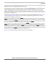
24.4.2.1 Transmitter
The transmitter is enabled through the UART command register (UCRn). When it is ready to accept a
character, UART sets USRn[TXRDY]. The transmitter converts parallel data from the CPU to a serial bit
stream on UTXDn. It automatically sends a start bit followed by the programmed number of data bits, an
Divider
66MHz
32 x 9600[]
------------------------------- 215 decimal()0x00D6 hexadecimal()== =
Baudrate
f
extc
(16 or 1)
---------------------
=
Receiver Shift Register
UART Command Register (UCRn)W
UART Status Register (USRn)
R
Transmitter Shift Register
UART Mode Register 1 (UMR1n)R/W
UART Mode Register 2 (UMR2n)R/W
Transmitter Holding Register
W
Receiver Holding Register 3
Receiver Holding Register 2
Receiver Holding Register 1
R
UART Receive
UART
Buffer (URBn)
(4 Registers)
UARTn
External
Interface
Transmit Buffer
(UTBn)
(2 Registers)
FIFO
URXDn
UTXDn