


UART Modules
MCF52211 ColdFire® Integrated Microcontroller Reference Manual, Rev. 2
24-26 Freescale Semiconductor
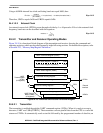
24.4.5 Bus Operation
This section describes bus operation during read, write, and interrupt acknowledge cycles to the UART
module.
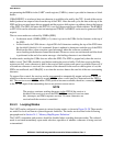
24.4.5.1 Read Cycles
The UART module responds to reads with byte data. Reserved registers return zeros.
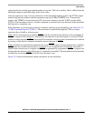
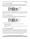
24.4.5.2 Write Cycles
The UART module accepts write data as bytes only. Write cycles to read-only or reserved registers
complete normally without an error termination, but data is ignored.
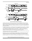
24.5 Initialization/Application Information
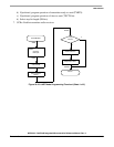
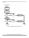
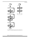
The software flowchart, Figure 24-25, consists of:
• UART module initialization—These routines consist of SINIT and CHCHK (See Sheet 1 p. 24-29
and Sheet 2 p. 24-30). Before SINIT is called at system initialization, the calling routine allocates
2 words on the system FIFO. On return to the calling routine, SINIT passes UART status data on
the FIFO. If SINIT finds no errors, the transmitter and receiver are enabled. SINIT calls CHCHK
to perform the checks. When called, SINIT places the UART in local loopback mode and checks
for the following errors:
— Transmitter never ready
— Receiver never ready
— Parity error
— Incorrect character received
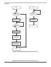
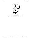
• I/O driver routine—This routine (See Sheet 4 p. 24-32 and Sheet 5 p. 24-33) consists of INCH, the
terminal input character routine which gets a character from the receiver, and OUTCH, which
sends a character to the transmitter.
• Interrupt handling—This consists of SIRQ (See Sheet 4 p. 24-32), which is executed after the
UART module generates an interrupt caused by a change-in-break (beginning of a break). SIRQ
then clears the interrupt source, waits for the next change-in-break interrupt (end of break), clears
the interrupt source again, then returns from exception processing to the system monitor.
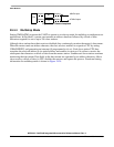
24.5.1 Interrupt and DMA Request Initialization
24.5.1.1 Setting up the UART to Generate Core Interrupts
The list below provides steps to properly initialize the UART to generate an interrupt request to the
processor’s interrupt controller. See Section 14.3.6.1, “Interrupt Sources,” for details on interrupt
assignments for the UART modules.
1. Initialize the appropriate ICRx register in the interrupt controller.
2. Unmask appropriate bits in IMR in the interrupt controller.