


Analog-to-Digital Converter (ADC)
MCF52211 ColdFire® Integrated Microcontroller Reference Manual, Rev. 2
Freescale Semiconductor 26-5
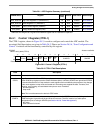
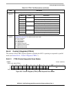
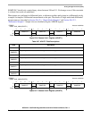
26.4.2 Control 2 Register (CTRL2)
The structure of the CTRL2 register depends on whether the ADC is operating in sequential or parallel
mode (see Section 26.4.1, “Control 1 Register (CTRL1)”).
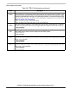
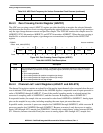
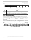
26.4.2.1 CTRL2 Under Sequential Scan Modes
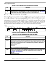
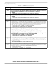
7–4
CHNCFG
Channel Configure. This field configures the inputs for single-ended or differential conversions:
2–0
SMODE
Scan Mode Control. This field controls the scan mode of the ADC module. See Section 26.5.6, “Scan
Configuration and Control” for details on each scan mode.
000 Once sequential
001 Once parallel
010 Loop sequential
011 Loop parallel
100 Triggered sequential
101 Triggered parallel (default)
110 Reserved; do not use
111 Reserved; do not use
IPSBAR
Offset:
0x19_0002 (CTRL2)
Access: read/write
15 14 13 12 11 10 9 8 7 6 5 4 3 2 1 0
R 0 0 0 0 0 000000
DIV
W
Reset0 0 0 0 00000000 0 0 1 0
Figure 26-3. Control 2 Register (CTRL2) Under Sequential Scan Modes
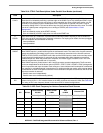
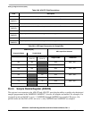
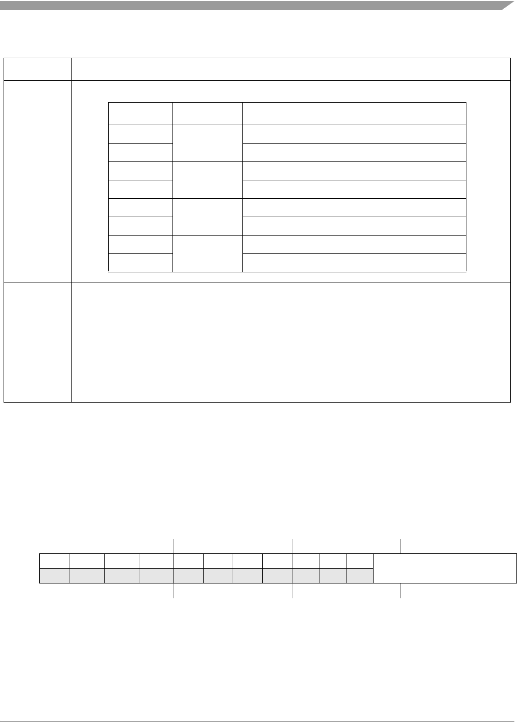
Table 26-2. CTRL1 Field Descriptions (continued)
Field Description
CHNCFG Inputs Description
xxx1 AN0–AN1 Configured as differential pair (AN0 is + and AN1 is –)
xxx0 Both configured as single ended inputs
xx1x AN2–AN3 Configured as differential pair (AN2 is + and AN3 is –)
xx0x Both configured as single ended inputs
x1xx AN4–AN5 Configured as differential pair (AN4 is + and AN5 is –)
x0xx Both configured as single ended inputs
1xxx AN6–AN7 Configured as differential pair (AN6 is + and AN7 is –)
0xxx Both configured as single ended inputs