


Clock Module
MCF52211 ColdFire® Integrated Microcontroller Reference Manual, Rev. 2
Freescale Semiconductor 6-5
6.6 Signal Descriptions
The clock module signals are summarized in Table 6-2 and a brief description follows. For more detailed
information, refer to Chapter 2, “Signal Descriptions.”
6.6.1 EXTAL
This input is driven by an external clock except when used as a connection to the external crystal when
using the internal oscillator.
6.6.2 XTAL
This output is an internal oscillator connection to the external crystal. If CLKMOD0 is driven low during
reset, XTAL is sampled to determine clocking mode.
6.6.3 CLKOUT
This output reflects the internal system clock.
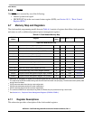
6.6.4 CLKMOD[1:0]
These inputs are used to select the clock mode during chip configuration as described in Table 6-3.
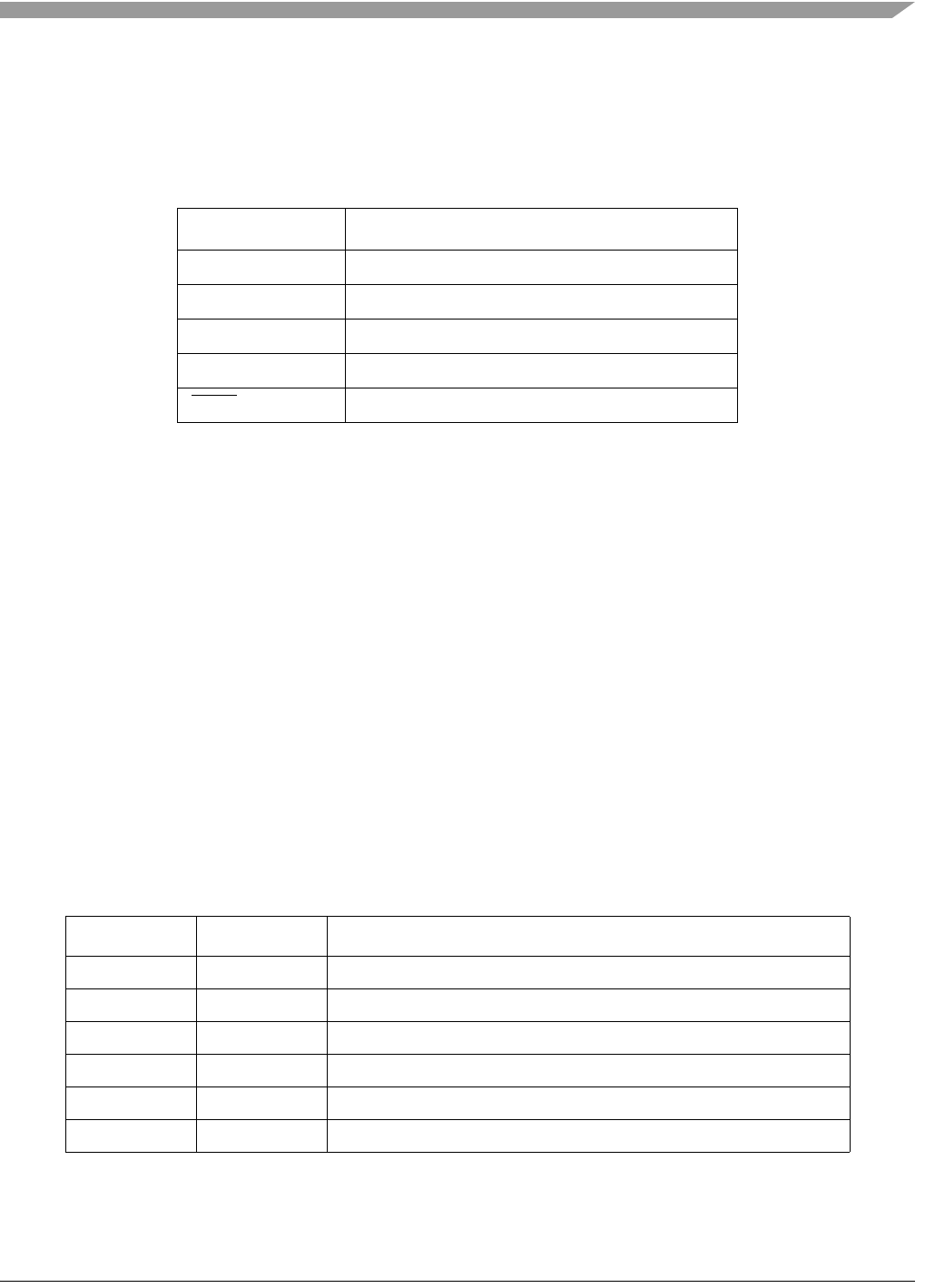
Table 6-2. Signal Properties
Name Function
EXTAL Oscillator or clock input
XTAL Oscillator output
CLKOUT System clock output
CLKMOD[1:0] Clock mode select inputs
RSTO
Reset signal from reset controller
Table 6-3. Clocking Modes
CLKMOD[1:0] XTAL Clocking Mode
00 0 PLL disabled, clock driven by external oscillator
00 1 PLL disabled, clock driven by on-chip oscillator
01 N/A PLL disabled, clock driven by external crystal
10 0 PLL in normal mode, clock driven by external oscillator
10 1 PLL in normal mode, clock driven by on-chip oscillator
11 N/A PLL in normal mode, clock driven by external crystal