


UART Modules
MCF52211 ColdFire® Integrated Microcontroller Reference Manual, Rev. 2
Freescale Semiconductor 24-9
24.3.4 UART Clock Select Registers (UCSRn)
The UCSRs select an external clock on the DTIN input (divided by 1 or 16) or a prescaled internal bus
clock as the clocking source for the transmitter and receiver. See Section 24.4.1, “Transmitter/Receiver
Clock Source.” The transmitter and receiver can use different clock sources. To use the internal bus clock
for both, set UCSRn to 0xDD.
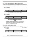
24.3.5 UART Command Registers (UCRn)
The UCRs, shown in Figure 24-7, supply commands to the UART. Only multiple commands that do not
conflict can be specified in a single write to a UCRn. For example,
RESET TRANSMITTER and ENABLE
TRANSMITTER cannot be specified in one command.
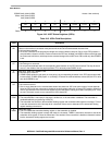
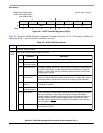
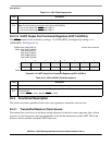
1
FFULL
FIFO full.
0 The FIFO is not full but may hold up to two unread characters.
1 A character was received and the receiver FIFO is now full. Any characters received when the FIFO is full are lost.
0
RXRDY
Receiver ready.
0 The CPU has read the receive buffer and no characters remain in the FIFO after this read.
1 One or more characters were received and are waiting in the receive buffer FIFO.
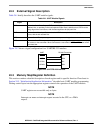
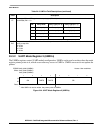
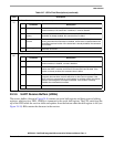
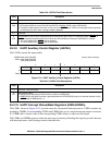
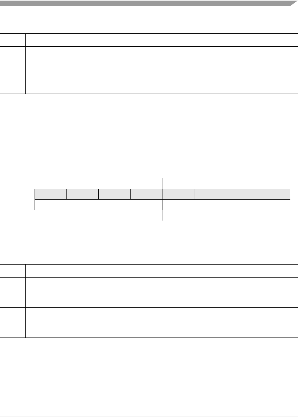
IPSBAR
Offset:
0x00_0204 (UCSR0)
0x00_0244 (UCSR1)
0x00_0284 (UCSR2)
Access: User write-only
76543210
R
W RCS TCS
Reset: See Note See Note
Note: The RCS and TCS reset values are set so the receiver and transmiter use the prescaled internal bus
clock as their clock source.
Figure 24-6. UART Clock Select Registers (UCSRn)
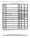
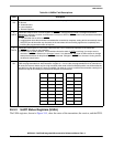
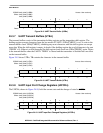
Table 24-6. UCSRn Field Descriptions
Field Description
7–4
RCS
Receiver clock select. Selects the clock source for the receiver.
1101 Prescaled internal bus clock (f
sys
)
1110 DTINn divided by 16
1111 DTINn
3–0
TCS
Transmitter clock select. Selects the clock source for the transmitter.
1101 Prescaled internal bus clock (f
sys
)
1110 DTINn divided by 16
1111 DTINn
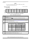
Table 24-5. USRn Field Descriptions (continued)
Field Description