


DMA Controller Module
MCF52211 ColdFire® Integrated Microcontroller Reference Manual, Rev. 2
17-2 Freescale Semiconductor
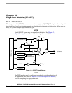
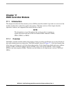
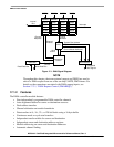
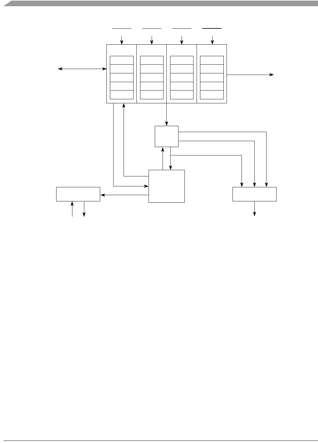
Figure 17-1. DMA Signal Diagram
NOTE
Throughout this chapter, the terms external request and DREQ are used to
refer to a DMA request from one of the on-chip UARTS, DMA timers. For
details on the connections associated with DMA request inputs, see
Section 17.3.1, “DMA Request Control (DMAREQC).”
17.1.2 Features
The DMA controller module features:
• Four independently programmable DMA controller channels
• Auto-alignment feature for source or destination accesses
• Dual-address transfers
• Channel arbitration on transfer boundaries
• Data transfers in 8-, 16-, 32-, or 128-bit blocks using a 16-byte buffer
• Continuous-mode or cycle-steal transfers
• Independent transfer widths for source and destination
• Independent source and destination address registers
• Modulo addressing on source and destination addresses
• Automatic channel linking
MUX
Arbitration/
Bus Interface
Data Path
Control
Internal
ChannelChannel
MUX
Registered
Data Path
SAR0
DAR0
BCR0
DCR0
DSR0
Channel 0
Interrupts
SAR1
DAR1
BCR1
DCR1
DSR1
Channel 1
SAR2
DAR2
BCR2
DCR2
DSR2
Channel 2
SAR3
DAR3
BCR3
DCR3
DSR3
Channel 3
Bus
Attributes
Current Master Attributes
Write Data Bus
Read Data Bus
System Bus Address
System Bus Size
Channel
Enables
Requests
Bus Signals
Control
Control
DREQ0 DREQ1 DREQ2
DREQ3