


MCF52211 ColdFire® Integrated Microcontroller Reference Manual, Rev. 2
Freescale Semiconductor 24-1
Chapter 24
UART Modules
24.1 Introduction
This chapter describes the use of the three universal asynchronous receiver/transmitters (UARTs) and
includes programming examples.
NOTE
The designation n appears throughout this section to refer to registers or
signals associated with one of the three identical UART modules: UART0,
UART1, or UART2.
24.1.1 Overview
The internal bus clock can clock each of the three independent UARTs, eliminating the need for an external
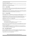
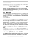
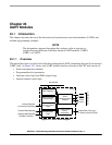
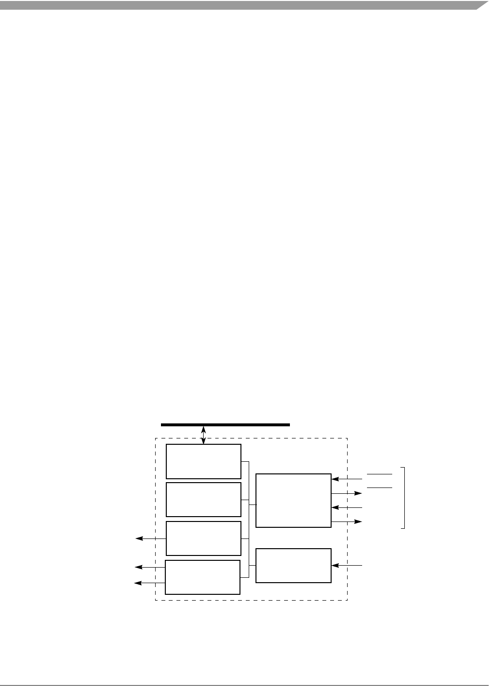
UART clock. As Figure 24-1 shows, each UART module interfaces directly to the CPU and consists of:
• Serial communication channel
• Programmable clock generation
• Interrupt control logic and DMA request logic
• Internal channel control logic
Figure 24-1. UART Block Diagram
Serial
Interrupt Control
Logic
Internal Channel
Control Logic
Programmable
Clock
Communications
Channel
Generation
UART
Internal Bus Clock (f
sys
)
or External Clock (DTINn)
DMA Request
Logic
Transmit DMA Request
Receive DMA Request
Interrupt Request
(to Interrupt Controller)
(To DMA Controller)
External Signals
UART Registers
UCTSn
URTSn
URXDn
UTXDn
Internal Bus