


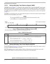


Backup Watchdog Timer (BWT) Module
MCF52211 ColdFire® Integrated Microcontroller Reference Manual, Rev. 2
7-6 Freescale Semiconductor
7.3 Functional Description
When the BWT is properly enabled, it loads the value in WMR[WM] into WCNTR[WC] and begins to
decrement WCNTR[WC]. If WCNTR[WC] reaches zero, the BWT asserts a system reset. To prevent this
reset, the BWT requires the software to write 0x5555 and 0xAAAA, in that order, to the WSR. This
procedure, referred to as servicing the BWT, reinitializes the value of WCNTR[WC] to the value in
WMR[WM]. This logic helps guard against runaway code.
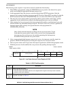
The following procedure summarizes how to enable and service the BWT properly.
1. Select the desired clock source for the BWT from within the clock module (see Chapter 6, “Clock
Module”).
2. Write to the BWCR (see Section 6.7.1.10, “Backup Watchdog Timer Control Register (BWCR)”)
with the proper values for the chosen clock source.
3. Determine the desired timeout period for the BWT, and write it to the WMR. This step is
recommended even if the default values are acceptable, to lock the register against accidental
writes by runaway code.
4. Write to the WCR with WCR[EN]=1 and the WAIT, DOZE, and STOP bits configured as desired.
5. To prevent a reset, service the BWT by writing 0x5555 and 0xAAAA, in that order, to the WSR
before the timeout period is reached.