


Analog-to-Digital Converter (ADC)
MCF52211 ColdFire® Integrated Microcontroller Reference Manual, Rev. 2
26-18 Freescale Semiconductor
5. Current mode
• Normal current mode is used to power the converters at clock rates above 100 kHz.
• Standby current mode uses less power and is engaged only when the ADC clock is at 100 kHz. The
current mode active does not affect the number of ADC clock cycles required to do a conversion
or the accuracy of a conversion. The ADC module may change the current mode when idle as part
of the power saving strategy. Both converters are in the same current mode at all times.
In addition to the power modes, there is startup delay:
• Auto power-down and auto standby power modes cause a startup delay when the ADC module
goes between the idle and active states to allow time to switch clocks or power configurations. The
number of ADC clocks used in the startup delay is defined by the PUDELAY field.
See the discussion of power modes in the Functional Description Section 26.5, “Functional Description”
for details of the 5 power modes and how to configure them. See Section 26.5.9, “ADC Clock,” for a more
detailed description of the clocking system and the control of current mode.
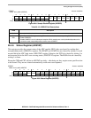
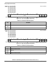
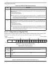
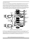
IPSBAR
Offset: 0x19_0052 (POWER)
Access: read/write
1514131211109876543210
R
ASB
0 0 PSTS2 PSTS1 PSTS0
PUDELAY APD
PD2 PD1 PD0
W
Reset000 0 0 0 0011010111
Figure 26-16. Power Control Register (POWER)
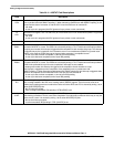
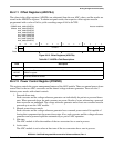
Table 26-18. POWER Field Descriptions
Field Description
15
ASB
Auto Standby bit. This bit selects auto standby mode. ASB is ignored if APD is set. When the ADC is idle,
auto standby mode selects the standby clock as the ADC clock source and puts the converters into standby
current mode. At the start of any scan, the conversion clock is selected as the ADC clock and a delay of
PUDELAY ADC clock cycles is imposed for current levels to stabilize. After this delay, the ADC initiates the
scan. When the ADC returns to the idle state, the standby clock is again selected and the converters revert
to the standby current state.
0 Auto standby mode disabled
1 Auto standby mode enabled
14–13 Reserved, should be cleared.
12
PSTS2
Voltage Reference Power Status bit.
0 Voltage reference circuit is currently enabled
1 Voltage reference circuit is currently disabled
11
PSTS1
Converter B Power Status bit. This bit is asserted immediately after PD1 is set. It is deasserted PUDELAY
ADC clock cycles after PD1 is cleared if APD is 0. This bit can be read as a status bit to determine when the
ADC is ready for operation. During auto power-down mode, this bit indicates the current powered state of
converter B.
0 ADC converter B is currently enabled
1 ADC converter B is currently disabled