


I
2
C Interface
MCF52211 ColdFire® Integrated Microcontroller Reference Manual, Rev. 2
Freescale Semiconductor 25-13
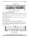
25.3.8 Handshaking and Clock Stretching
The clock synchronization mechanism can acts as a handshake in data transfers. Slave devices can hold
SCL low after completing one byte transfer. In such a case, the clock mechanism halts the bus clock and
forces the master clock into wait states until the slave releases SCL.
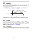
Slaves may also slow down the transfer bit rate. After the master has driven SCL low, the slave can drive
SCL low for the required period and then release it. If the slave SCL low period is longer than the master
SCL low period, the resulting SCL bus signal low period is stretched.
25.4 Initialization/Application Information
The following examples show programming for initialization, signaling START, post-transfer software
response, signaling STOP, and generating a repeated START.
25.4.1 Initialization Sequence
Before the interface can transfer serial data, registers must be initialized:
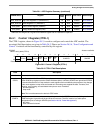
1. Set I2FDR[IC] to obtain SCL frequency from the system bus clock. See Section 25.2.2, “I2C
Frequency Divider Registers (I2FDRn).”
2. Update the I2ADR to define its slave address.
3. Set I2CR[IEN] to enable the I
2
C bus interface system.
4. Modify the I2CR to select or deselect master/slave mode, transmit/receive mode, and
interrupt-enable or not.
NOTE
If I2SR[IBB] is set when the I
2
C bus module is enabled, execute the
following pseudocode sequence before proceeding with normal
initialization code. This issues a STOP command to the slave device,
placing it in idle state as if it were power-cycled on.
I2CR = 0x0
I2CR = 0xA0
dummy read of I2DR
I2SR = 0x0
I2CR = 0x0
I2CR = 0x80 ; re-enable
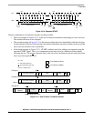
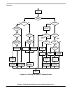
25.4.2 Generation of START
After completion of the initialization procedure, serial data can be transmitted by selecting the master
transmitter mode. On a multiple-master bus system, I2SR[IBB] must be tested to determine whether the
serial bus is free. If the bus is free (IBB is cleared), the START signal and the first byte (the slave address)
can be sent. The data written to the data register comprises the address of the desired slave and the lsb
indicates the transfer direction.
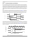
The free time between a STOP and the next START condition is built into the hardware that generates the
START cycle. Depending on the relative frequencies of the system clock and the SCL period, the processor