Chapter 1
Overview
I/O Subsystem
49
SBA Chip: CC-to-Ropes
The SBA chip communicates with the CC on the cell board via a pair of high-speed serial unidirectional links
known as HSS or E-links. Each unidirectional E-link consists of 20 serial 8b/10b encoded differential data bits
operating at 2.36 GT/s. This yields a peak total bidirectional HSS link bandwidth of 8.5 GB/s. Internally, SBA
routes this high-speed data to/from one of two rope units. Each rope unit spawns four single ropes and four fat
ropes. A maximum of 2 like ropes can connect to an LBA.
In a default configuration, ropes operate with a 133 MHz clock and so have 266 MT/s for a peak bandwidth
266 MB/s per single rope. In the enhanced configuration, ropes operate with a 266 MHz clock and so have 533
MT/s for a peak bandwidth 533 MB/s per single rope. On the SIOBP, firmware is expected to always configure
the 266 MHz enhanced ropes.
Ropes can be connected to LBAs either individually or in pairs. A single rope can sustain up to PCI 4x data
rates (full bandwidth support for a 64-bit PCI card at 33 or 66 MHz or for a 64-bit PCI-X card at 66 MHz or for
a 32-bit PCI-X card at 133 MHz). A dual rope or fat rope can sustain PCI 8x data rates (64-bit PCI-X card at
133 MHz). A dual fat rope can sustain PCI 16x data rates (64-bit PCI-X card at 266 MHz). Because of the
internal architecture of the SBA, when two ropes are combined, they must be adjacent even/odd pairs. Ropes
0 and 1 can be combined, but not 1 and 2. The two paired ropes must also be of the same type: either single or
fat.
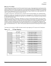
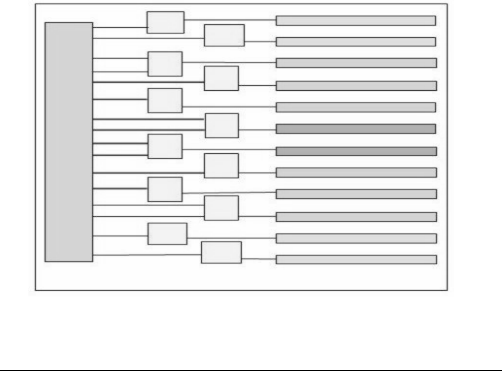
The location of the ropes on the SBA chip determines the rope mapping to PCI slots on the I/O backplane.
Figure 1-10 I/O Rope Mapping
LBA
LBA
LBA
LBA
LBA
LBA
LBA
LBA
SBA
0
1
2
3
4
5
6
7
14
15
13
12
10
11
9
8
HMIOB
Slot 0 (PCI-X 133/66
Slot 1(PCI-X 133/66
Slot 2(PCI-X 133 MHz)
Slot 3(PCI-X 133 MHz)
Slot 4(PCI-X 133 MHz)
Slot 5(PCI-X 266 MHz)
Slot 6(PCI-X 266 MHz)
Slot 7(PCI-X 133 MHz)
Slot 8(PCI-X 133 MHz)
Slot 9(PCI-X 133 MHz)
Slot 10 (PCI-X 133/66
Slot 11 (PCI-X 133/66


