


Chapter 3
Installing the System
Setting Up the System
97
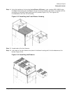
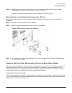
Step 6. To secure the side bezels to the side skins, attach the blower bracket locks (HP part number
A5201-00268) to the front and back blowers using a T-20 driver.
There are two blower bracket locks on the front blowers and two on the rear.
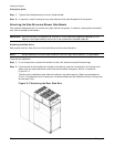
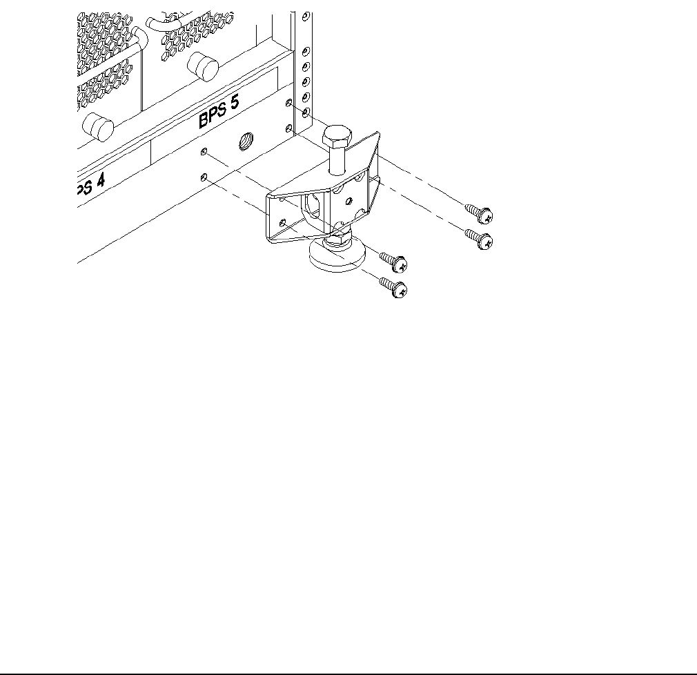
Attaching the Leveling Feet and Leveling the Cabinet
After positioning the cabinet to its final position, attach and adjust the leveling feet using the following
procedure:
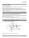
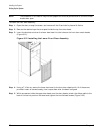
Step 1. Remove the leveling feet from their packages.
Step 2. Attach the leveling feet to the cabinet using four T-25 screws.
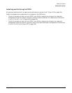
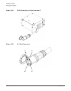
Figure 3-20 Attaching the Leveling Feet
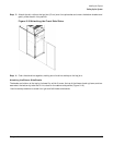
Step 3. Screw down each leveling foot clockwise, until it is in firm contact with the floor. Adjust each foot
until the cabinet is level.
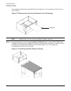
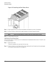
Installing the Front Door Bezels and the Front and Rear Blower Bezels
Each cabinet has two doors: one at the front and one at the back. The back door is shipped on the chassis and
requires no assembly. The front door, which is also shipped on the chassis, requires the assembly of two
plastic bezels to its front surface and a cable from the door to the upper front bezel. In addition, you need to
install bezels that fit over the blowers at the front and back of the cabinet.
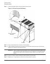
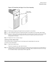
Installing the Front Door Bezels
The front door assembly includes two cosmetic covers, a control panel, and a key lock. Installing the front door
involves connecting the control panel ribbon cable from the chassis to the control panel and mounting the two
plastic bezels onto the metal chassis door.